Buy Boards & Parts:
www.beezar.com
www.beezar.com

The Starving Student Millett Hybrid PCB
Construction - PCB, Part 2
|
Building the PCB (continued) -
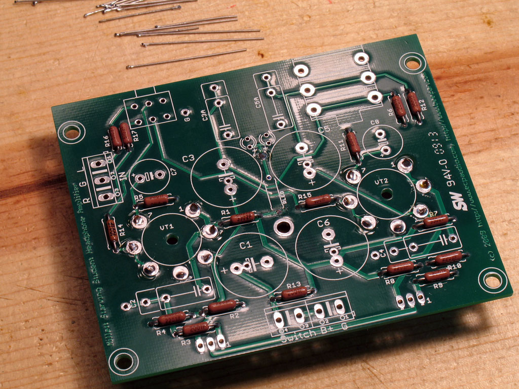
7. Install the tube sockets - After all of our work to drill the tube sockets and populating the PCB so far, hopefully the glue has cured and we're ready to install the tube sockets. As mentioned before, they go on the other side of the PCB which will be mounted up against the top plate of the custom Hammond case. IOW, the tube sockets will poke through the top of the case while the other parts will hang upside down inside the case. |
|
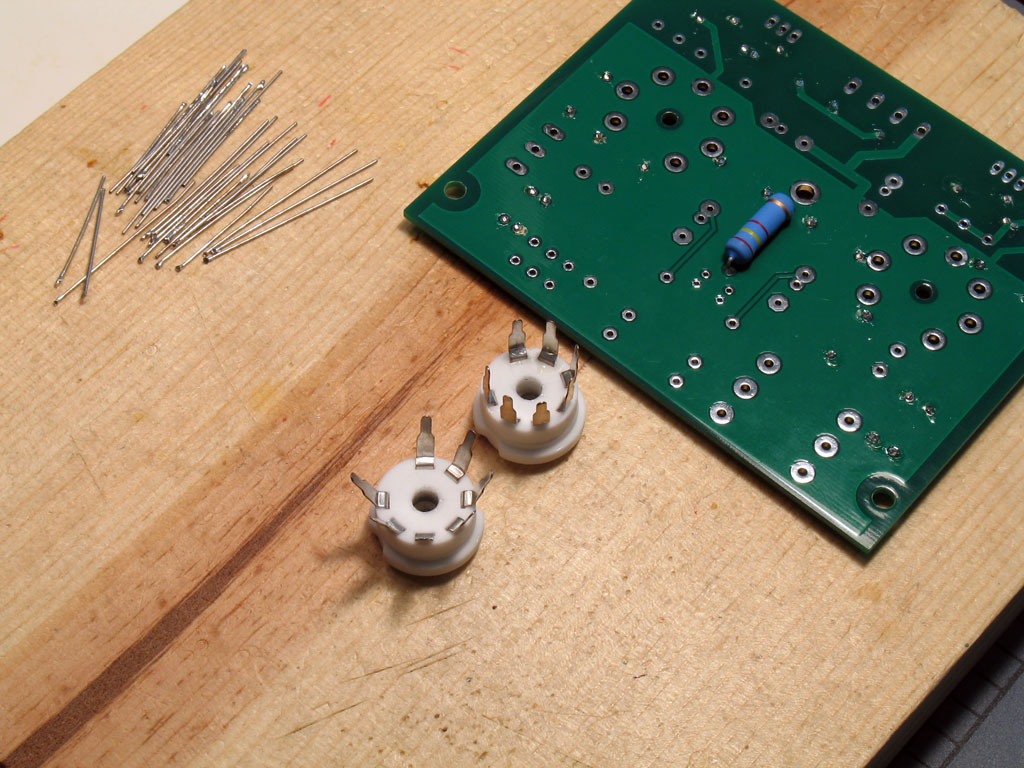 |
The tube sockets always come with the pins pretty much mashed into right angles from the sockets. However for proper mounting, they need to be splayed out at an angle. In fact, it works better to make sure the pins are splayed out a little further than the holes in the PCB. This way, you don't have to force the sockets from a "sprung" position to keep them lined up in the holes while soldering them. When the pins are splayed out slightly further than the holes, the act of forcing them into place compresses the socket into place. |
| Shown at left is an example of what the sockets may look like without bending the pins, and one with splayed out pins ready to be installed into the board.
Test fit the sockets/pins into the holes as you bend the pins out. It may take a few trys to get them all OK. Notice the alignment, too. If the top surface of the socket is not parallel to the board when trial fitting, then bend the pins out a little more on the high side. |
|
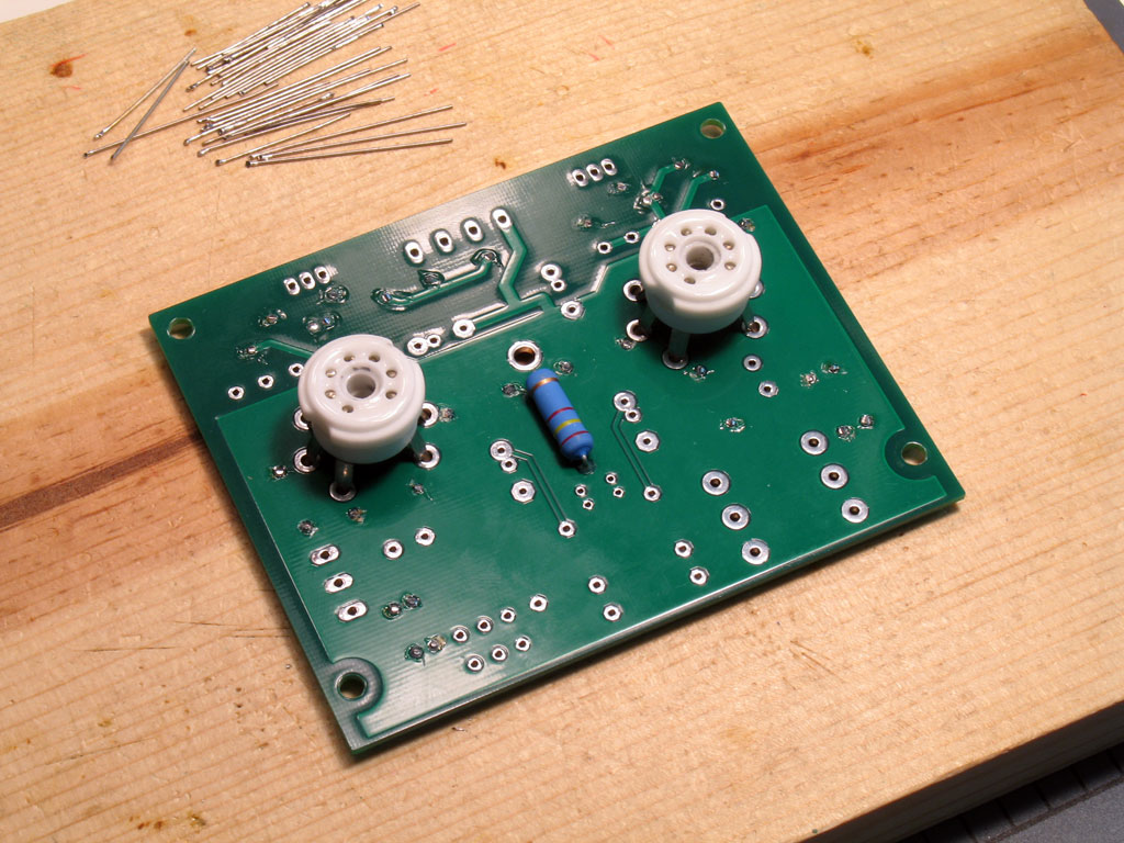 |
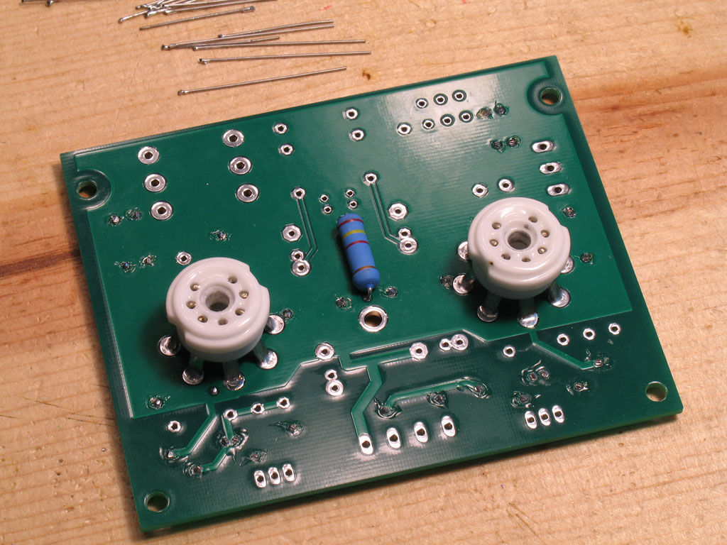
What you want to do is place both sockets into position, turn the PCB over, then solder. With both sockets in place, the PCB is actually supported by the sockets and it makes it a lot easier to solder - simply press down slightly on the board while soldering to make certain they're flush. Here are the sockets in position with the PCB ... |
 |
and turned over with the pins sticking out ready to be soldered ... |
| The tube sockets undergo a lot of stress, so we want these solder joints with the pins to be mechanically sound, in addition to being electrically sound. You should fill the holes completely so that there are no gaps in the solder. At the same time, you want to apply enough heat indirectly (to the solder) that there's wicking along the pins on the other side. A good joint will show the solder completely filled, wicked somewhat along the pins on the other side of the PCB, and will probably show a slight concave surface on the side where you apply the solder. The concave surface is the result of gravity pulling the solder down slightly through the hole. You'll make a mess if you try to get a flush surface with the solder - it will continue to run down the pins on the other side. After a few of them, you'll get the feel however. There's nothing wrong with going back and applying a bit more solder. | |
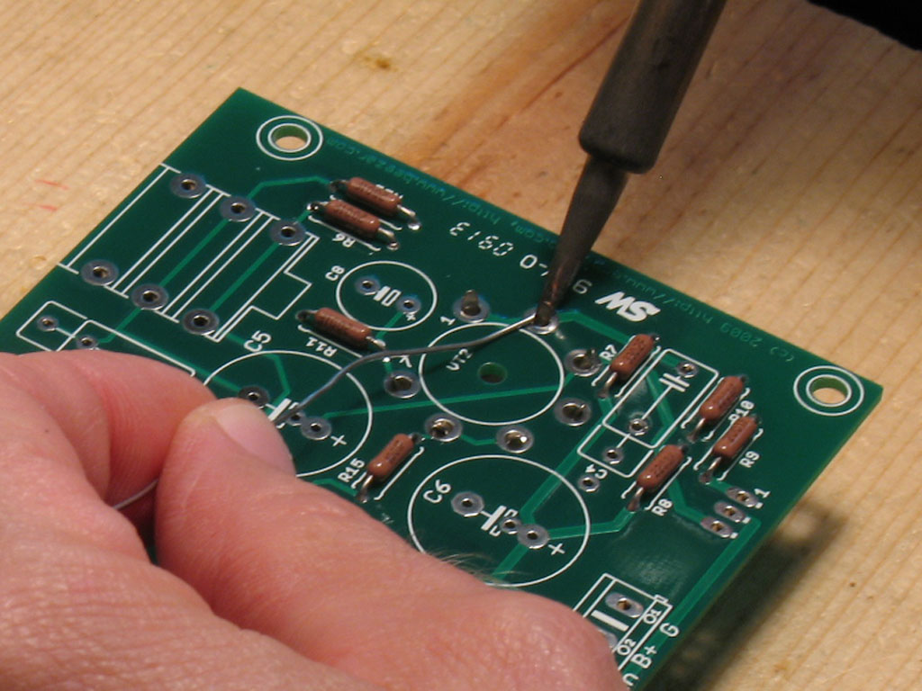 |
The best way I've found to solder the pins is shown at left. Hold the wedge tip on your soldering iron flush against the pin on the outside. Most of the hole opening will be on the other side of the pin surface. Apply solder to the side of the pin opposite of the soldering iron tip and feed the solder until the hole is filled. Keep the heat applied while mashing down slightly on the board. While still mashing down slightly, remove the iron and let the joint cool - it will take longer than you're used to because of the quantity of solder. |
|
Alternate from the pin on one side of the socket to the other - soldering opposite pins around the circle, so to speak. This is similar to tighteining the bolt pattern on your car's wheel when you change a tire - it keeps the forces symmetrical on the socket and helps to keep it straight. Once you've got two pins soldered on opposite sides of the socket circle, flip the PCB over occasionally to see if the sockets are straight. If the top surface of the socket is crooked (not parallel to the board), apply pressure in the opposite direction while soldering the remaining pins. A slight mis-alignment of the socket will cause the tips of the tubes to be pointing off-centered. Now, some of the glass in the tubes is crooked anyway, but it's still better to start out with a level tube socket surface than not.
|
|
 |
Here we see the sockets soldered in place on the pin side of the board. Note the slightly concave surface of the solder at each position. This is what they should look like to get the best mechanical and electrical connection. (Note the clear flux blobs around each pin - we'll need to clean that off.) |
 |
On the other side, you should be able to see the slight wicking along the pins. |
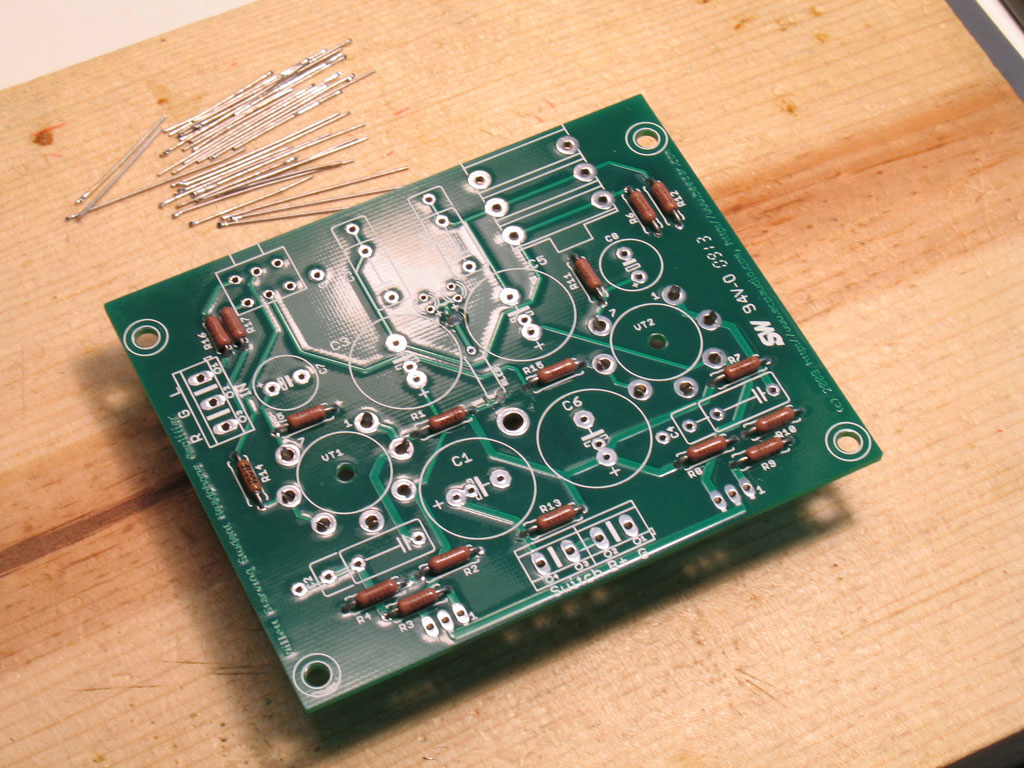
| At this point, it's best to clean the PCB on both sides in preparation for installing the rest of the parts. That's because you'll never get all that solder mess cleaned around those socket pins once you solder all the other parts into place.
(Ask me how I know that! )
I just use rubbing alcohol and an old toothbrush. Walmart sells some 97% pure isopropyl alcohol for about $1 a quart, so it's very cheap. It may take you several rinses to get all the flux off, but keep trying. Use a paper towel to blot up the alcohol - it should turn a dirty yellow where you're picking up the dissolved flux. Rinse, then blot dry, and repeat. When dry, dissolved flux will have a white powder appearance. So, if you still have some of that around the joints - you haven't rinsed enough - do it again. |
|
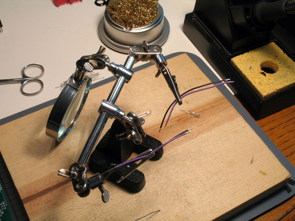 |
Anyway, here's two pairs of leads with the tips stripped and tinned.
Cheat and look forward to the photo showing the leads soldered into place below. You'll want to cut the leads at least this length, plus another inch or so to account for the vertical length through the socket. Do this by placing the wire along the PCB in the shape shown below, and then add the inch or two of extra and cut. Don't worry about getting them exact - we'll trim them to length once we get them threaded through. Be sure you have more length rather than less, though. |
 |
Here we see both wire leads soldered to the LED leads. Important - remember which lead is which! You'll need to trim the LED's leads as shown here, but once you do that, you'll no longer know which one was the longer lead (positive). I always use either black or green for ground, though. So in these pics, the black wire is negative and was soldered to the shorter lead. |
| Another important point - try to solder the leads on the top, bottom, or inside of the LED leads. If you solder the wire leads to the outside, then the overall diameter of the assembly might be too large to fit inside the tube socket hole! | |
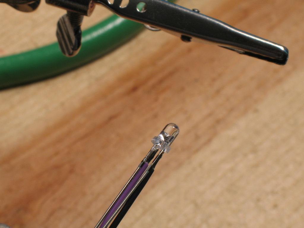 |
Here's a closeup of what I mean - soldering the wire leads have not added to the overall outside diameter. This one's slightly out of order because the LED leads have not been trimmed yet. Nip them carefully as close to the solder joint as you can: |
 |
Another trick shown here before threading the assembly through the tube socket hole and the PCB hole. Put heat shrink on one joint, only! This is small stuff, but I suppose a very small bit of electrical tape will work, too. |
| Again, nothing is going to come into contact with these leads once they're soldered into place and the LED is inside the socket. However, there's a good chance that they might be squeezed together. You only need to insulate one, though. That way, you haven't created a blob of tape/heat shrink so large that you can't get it into the tube socket hole. | |
 |
Here we see the LED's threaded through. You'll want to put the tip of the LED flush with the top surface of the socket. This will provide the best effect for tube lighting. There will be plenty of give in the LED/wire assembly, though, so if the LED sticks up past that a bit, it's OK. If your finger easily pushes them down, then so will the tubes, too. |
 |
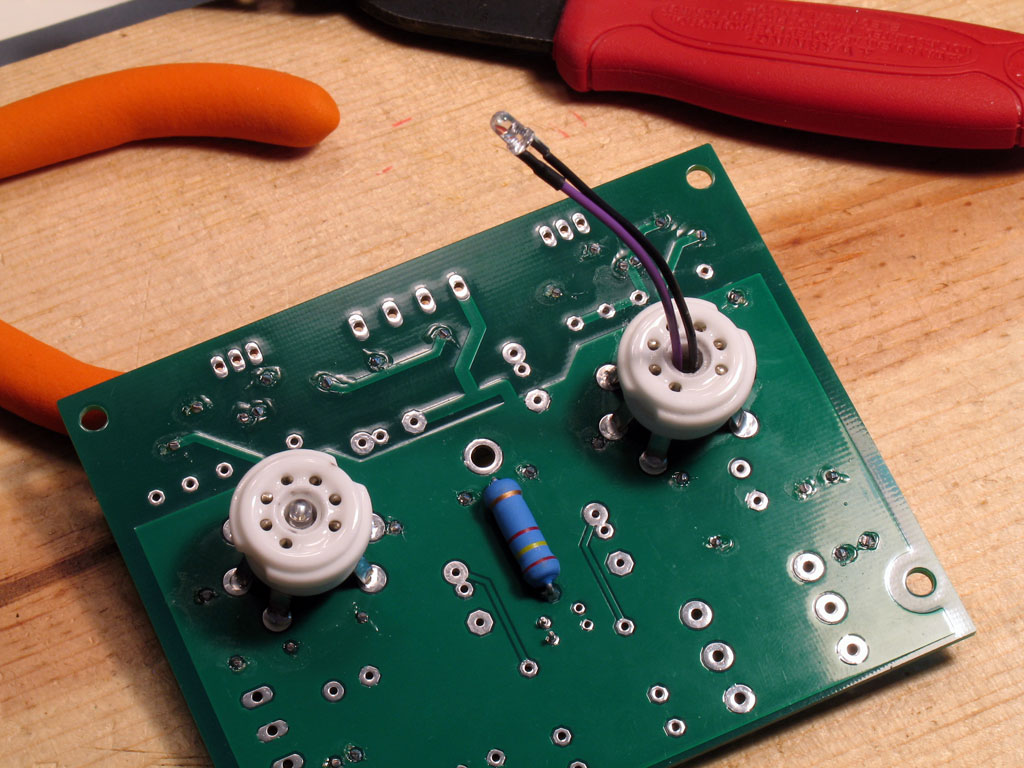
Finally, we'll flip the board over and position the leads into the proper pads. Remember, ground is negative and black in this case. So the purple wires have gone into the holes marked "+". Those should also correspond to the longest lead that was on the LEDs, too - way back when you first soldered the leads to the LED. (NOTE: Use this photo as an illustration of how to measure the lead length for the leads in the first step above.) |
| Trim the leads to length shown here, although a bit of slack is not going to hurt. You've got plenty of room with the taller capacitors and such that will go on later. Once you have them trimmed, slightly tin the leads and bend them down into a 90-degree angle. This makes it easier to fit them into the holes. Be careful, though - those pads are small!. Once you have them in, flip the board over and solder them into place. Once again, you should be able to push down on the board slightly to ensure that the tinned leads are pushed through completely and the insulation is flush with the board.
NOTE: I use 22ga Navshipps SPC wire for everything (John's Wire Shop on ebay). You might cheat here and use 24ga. That could make it a lot easier to thread through and solder the leads into the pads. 22 ga works fine, though, if you're careful not to make a blob when tinning the ends. |
|