Buy Boards & Parts:
www.beezar.com
www.beezar.com

The Starving Student Millett Hybrid PCB
Construction - Casework
|
Note: The construction tutorial assumes the use of the custom Beezar/Hammond case. Refer to the templates page for dimensions to use to drill your own Hammond case, if desired. Now on to the custom Beezar/Hammond case!
|
|
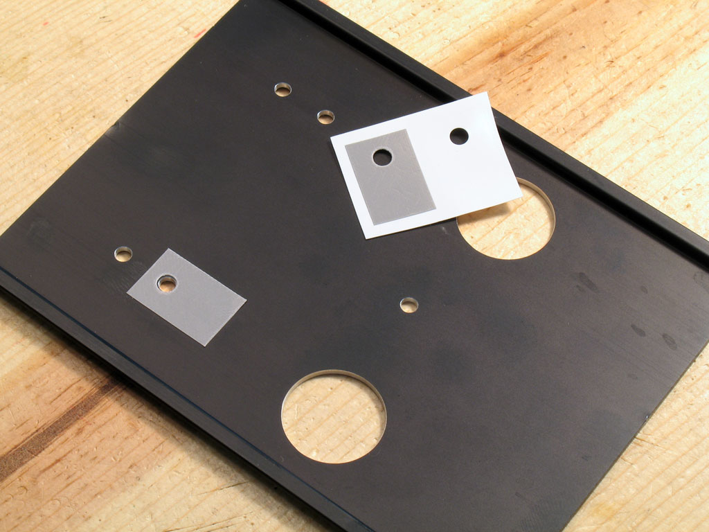 |
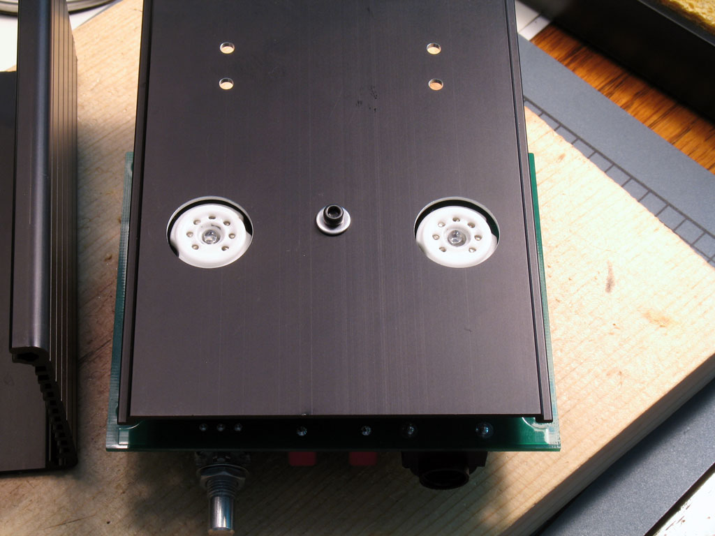
17. Prepare the Case Lid for Mounting to the PCB - Dsavitsk's SSMH PCB design depends on mounting the PCB to the case lid - everything is keyed off of that. Pictured below is the underside of the case lid. The first thing we want to do is to stick on the Bergquist thermal pads. These will come in the heat sink mounting kits at Beezar. |
 |
In this pic, I'm scrapping the anodizing away from the center hole. This hole will be used for a standoff that will be screwed to the center of the PCB. The pad is tied to the ground plane on the PCB, so if we make sure there's good contact with the case lid, that will increase our grounding resource. Looks terrible and it feels bad to do this to a brand new, custom-mfg'd case, but it's on the inside and no one will see. The benefit is enormous, though, and little touches like these will give us a very quiet amp while many others may have trouble with hum and noise on other P2P tube amps. |
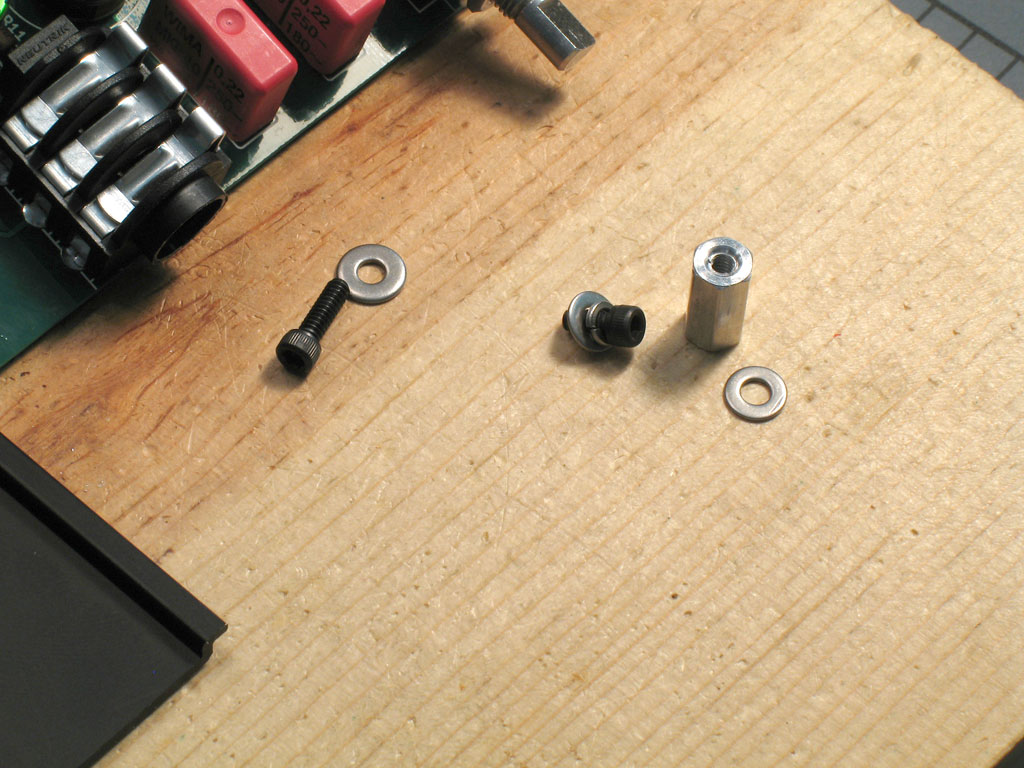 |
Here is the standoff assembly. This will be provided in the kit with several washers. At least one washer is required for spacing along with the standoff - perhaps two. The only caveat to this you'll see in a moment. There are some smaller washers you can pick from and you'll want to use those next to the PCB, or you may short the standoff against the tube LED resistor - more on that later. Essentially, what you see here is a 1/4" socket head screw, washer, and lock washer. Those will go on the parts (capacitors, etc.) side of the PCB. The small washer and standoff will go on the tube socket side. We use a lock washer here |
| because the screw on the PCB will be inaccessible from the outside, so we'll want that one to be locked in place. If it came loose, it might turn forever without un-screwing until we took the case apart. After that, we'll use just a flat washer and a longer screw from the outside to fasten the case lid to the standoff and thereby, the PCB. |
|
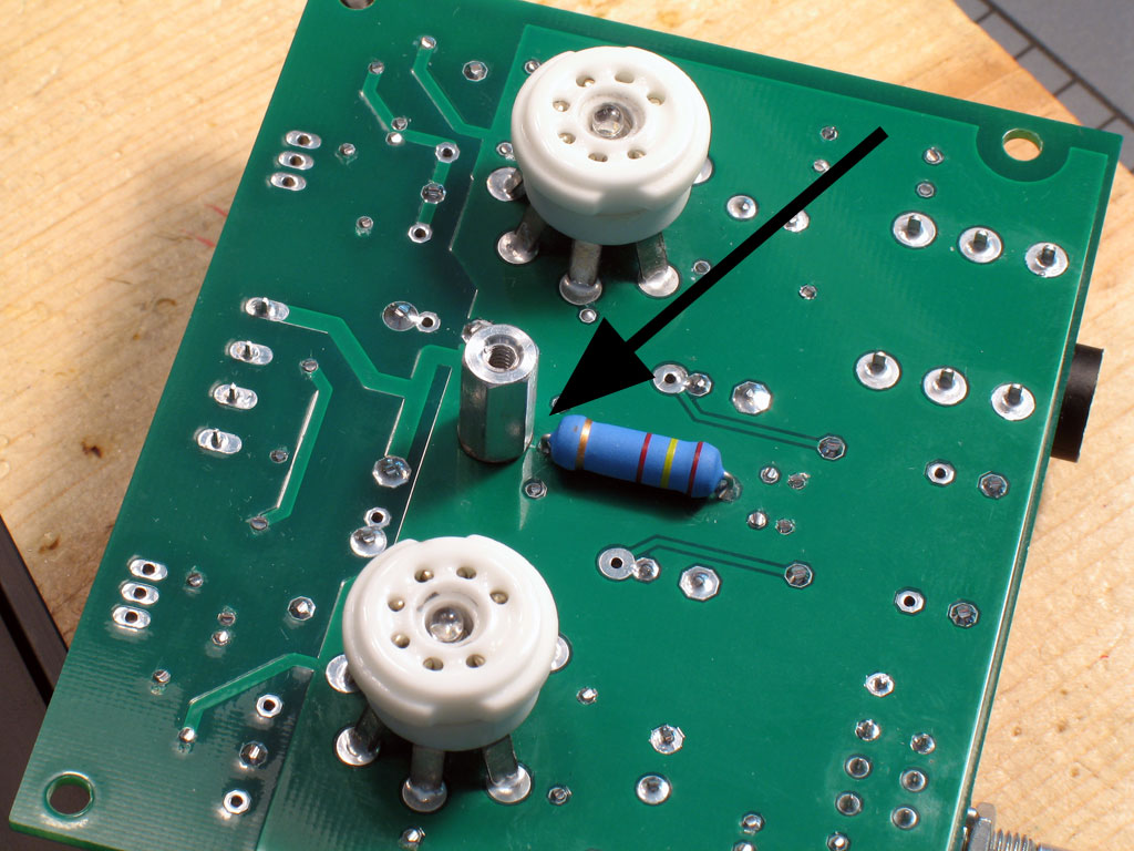 |
This is critical!! Note the spacing between the standoff, washer/spacer and the tube LED resistor lead. Be certain that you have some space here as shown. Otherwise, disaster will ensue. Note also that the flat side of the hex standoff is also facing the resistor lead. This is an additional insurance that a space is maintained. Note that a small washer must be used here - a regular sized flat washer will contact the lead, so don't use one. Nevertheless, the spacing with only the standoff is not sufficient, so some additional spacing is needed and the small washer provides that. |
 |
Here we see the other side of the PCB and the pad and snipped lead side of the tube LED resistor. Note the spacing - make sure yours is similar or disaster will ensue! |
 |
18. Screw the Case Lid to the PCB - As mentioned earlier, we use only a screw and a flat washer here - to ensure that if anything comes loose, it's the screw on the outside - the one we can get to! Depending on your build and your Beezar/Hammond custom case, you may need an additional washer/spacer on top of the standoff to make the best fit. I had to use one here, but I didn't on the first two I built. Again, YMMV, and actually - Hammond's MMV - due to extrusion differences, warping, etc. |
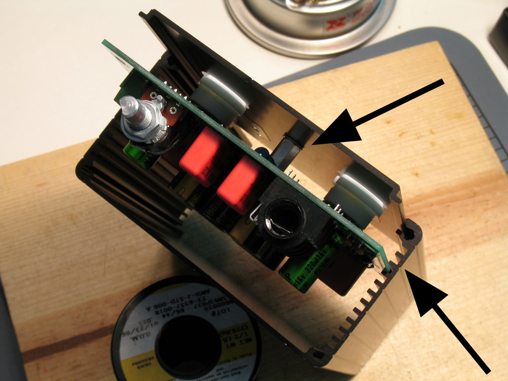 |
You'll want to trial fit a few times to get the spacing just right. When you do, the PCB should fit three slots down from the top of the case as shown here in a couple of views. Note the extra washer I had to use on this one. |
 |
Another view from the side. |
| OK, so now we have the case lid attached to the PCB with the center standoff! The next thing we want to do now is to complete the MOSFETs and heat sinks. This is much easier now than attempting to do it before, because the center standoff has determined the proper distance between the PCB, MOSFETs, and case lid. |
|
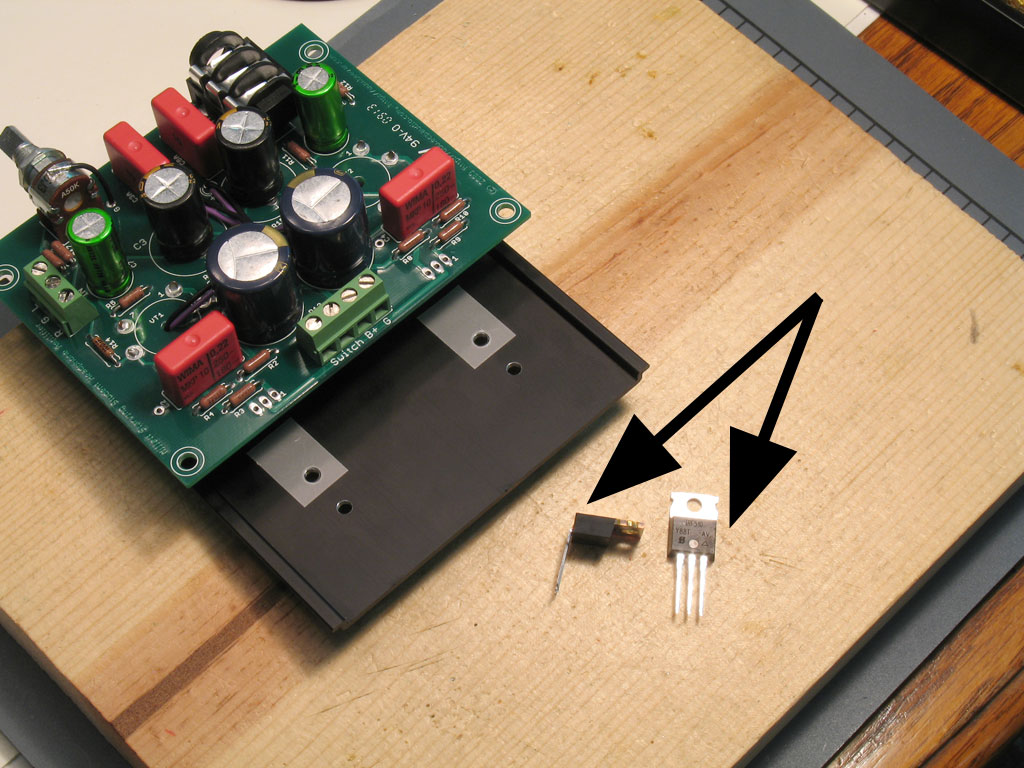 |
19. Insert the MOSFETs into the PCB Pads - With the PCB down to the 3rd slot on the case, there is only one way this will work - you must bend the MOSFET leads at 90 degrees directly at the plastic body. The pic shows the MOSFETs before and after. |
 |
Here we see one MOSFET inserted into the PCB pads, and one in an inbetween position. Work carefully doing this, or you'll scar up the Bergquist pads and perhaps loose heat transfer integrity, or loose insulation capability. Be patient - it may seem like the leads won't fit without a greater clearance between the lid and PCB, but they will. Ensure that the leads on the MOSFETs are straight and equally spaced - that will help things along. Once you get them inserted, it will have seemed so easy that you'll wonder why they didn't go in right away in the first place. |
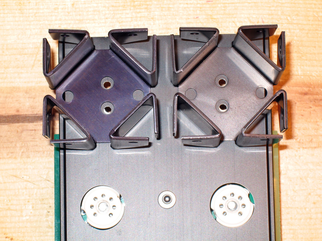 |
20. Install the Heat Sinks - Next comes what may be the most frustrating part of building the SSMH PCB - at least it is for me, usually. Before the frustrating part, though, let's review the heat sink solution for the SSMH PCB/case and note how the heat sinks are aligned to the case. Note that there are four mounting holes on each heat sink. We will only use two of them - the holes that are the closest to each other. However, note that the two holes perpendicular to those are offset - one is at a greater distance from the closer two holes than the other. Be sure that offset is to the outside on the SSMH case - |
| as shown here. Otherwise, the heat sinks will not fit together on the case lid. Once we've established that, our next task is to coat the bottom of the heat sinks with heat transfer goo. You see, the primary contact is between the MOSFETs, the Bergquist pad and the case lid. However, to enable the heat sinks to add their heat dissipation capability to the assembly, we need the best possible contact between the heat sinks and case lid. To do that, we need to use heat transfer goo between the heat sink surfaces and the case lid. I should've taken some photos, but I guess I got too frustrated again. Anyway, you'll want to use a toothpick or similar to spread - very thinly some heat transfer goo on the bottom surface of the heat sinks. Once you do that, you'll place each one in position - one at a time - until you insert the screw assemblies. In the heat sink kits that come with the SSMH kits, there's two longer screws (1/2") and two shorter screws (3/8"). Use the shorter screws on the second hole of the heat sink and use the long screws on the MOSFETs that use the first hole of the heat sinks. When inserting the screws, be sure you take the trouble to "seat" the shoulder washer into the MOSFET tab - it won't do it by itself. Essentially, we have a screw and washer on top of the heat sink and case lid, with a washer, lock washer and nut underneat. The MOSFETs are a bit different in that they present an additional thickness from the tab and also the shoulder washer - that's why the longer screws are used for the MOSFETs. |
|
 |
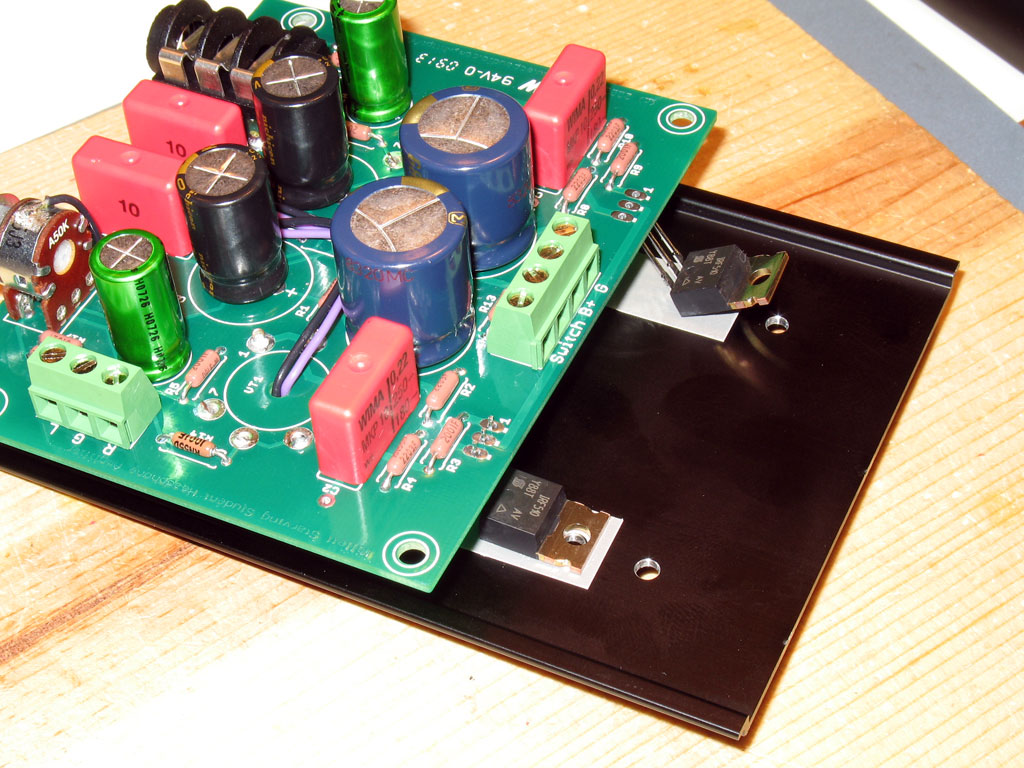
I'm sorry I skipped some needed photos, but here's the final assembly shown in detail. Now, why do I say this was frustrating? Because - once you put the heat transfer goo on the bottom of the heat sinks, they'll slide like they're on ice. All the while, you're trying to thread a couple of small screws through. When they slide, the goo goes all over the parts of the case that will be visible to everyone once completed. So, it's kind of like they're out to get you. Be patient, use a good pair of needlnose pliers to insert the screw assemblies - and be sure to go extra light on that heat transfer goo. If all of this scares you, then don't use the goo, period. |
| One thing you should be careful of, though - be sure you don't torque the MOSFETs down so tight that the tabs cut through the Bergquist pads - that would ruin the insulating capability and cause a short. So, tight and secure - but don't torque. | |
 |
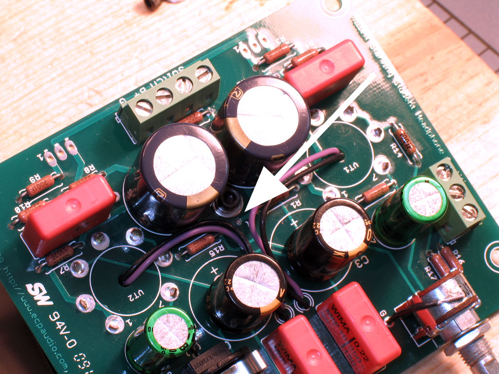
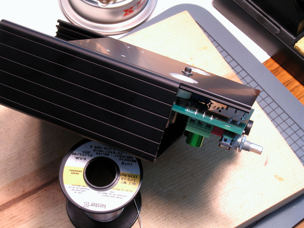
Oh - by the way: 21. Solder the MOSFET Leads to the Pads on the PCB - Piece of cake at this point, but don't forget to do it!! We're almost finished!! Here's the case lid/PCB assembly completely finished and inserted into the case for a trial fit (and intermediate admiration of our work). I used some super-duper heat transfer goo on this one - it's white. Eek! |