www.beezar.com

|
grubCableDAC!
Assembling a grubCableDAC is a little more trouble than simply populating the PCB, but not as much trouble as casing one up without the CableDAC option, IMHO. The reasons are that it's not as simple as the paint-by-number convenience that the PCB gives you.
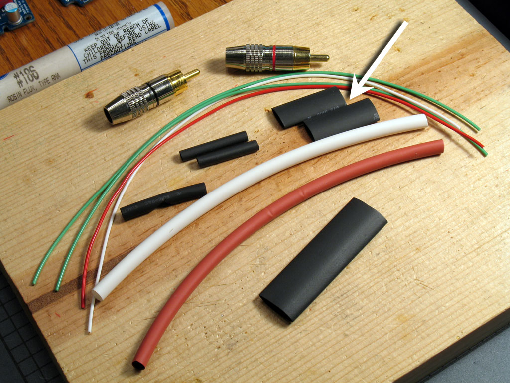
However, most of us have soldered leads, made cables, etc., before. The only difficult part is getting all of the parts right beforehand. Pictured below you see what's necessary to assemble the RCA leads for a CableDAC. With this, a USB pigtail, and the Hammond 1551HBTU case, I think you'll find it even easier and more flexible than the old-school method of casing up the DAC with regular case-mounted connetors.
The rest of this post will show you how to put all of the above together into a professional-looking set of output leads for a grubCableDAC. We'll start out soldering the RCA plugs. Be careful with these - unless you have some teflon-filled ones, the nylon filler is very easy to melt when you're soldering. If that happens, it will mess up the plug connector, rendering it useless. If you haven't by now, change your soldering iron back to its regular tip (the 900M-T-1.6D for me). What you need is fast, high heat. That will enable you to quickly heat up the localized solder joint areas instead of heating up the entire plug, thereby melting the nylon filler.
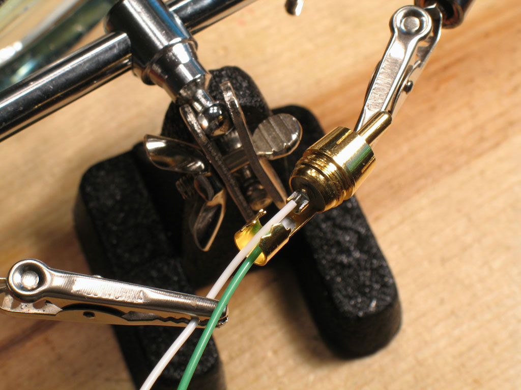
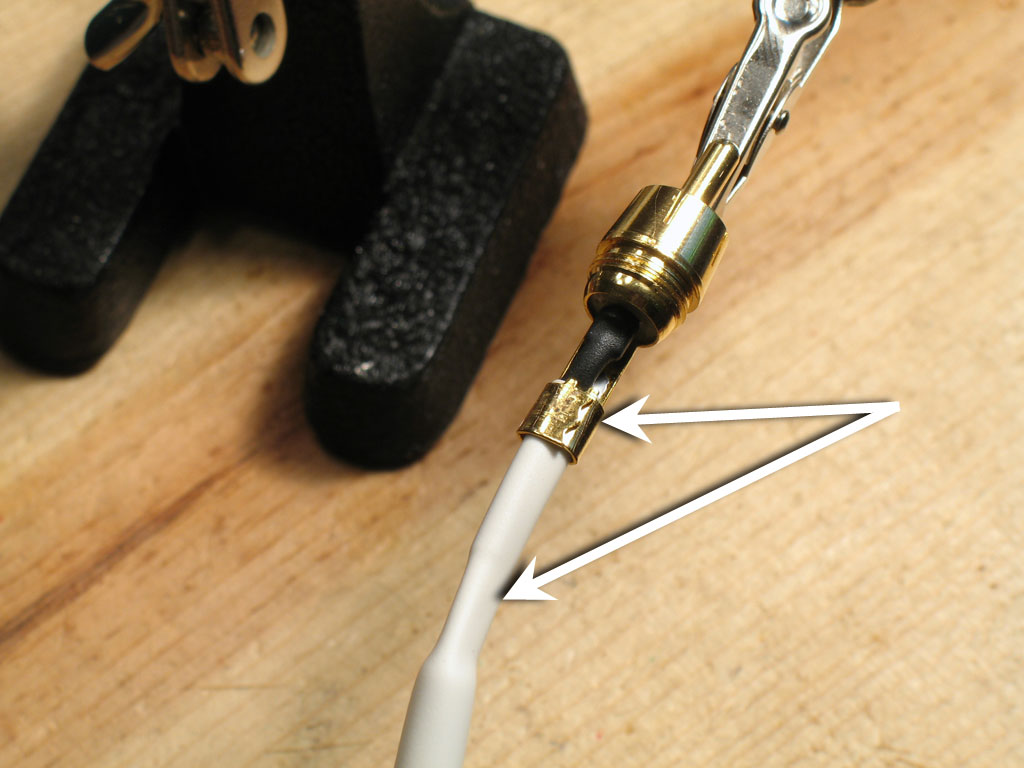
Next, we'll place one of the 1/8" x 1" long heat shrink pieces around the signal wire joint. Push this piece all the way up to the connector as shown with the white arrow. Heat and shrink into place.
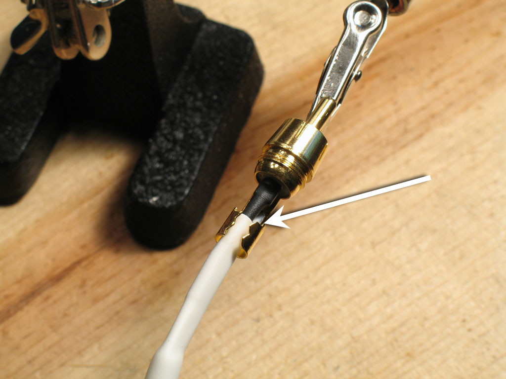
Place the 6" white piece of heat shrink over both leads and push it up as far as it will go. It will only go to the ground wire's solder joint, but that's far enough (white arrow). It will be locked into place with the ground tab crimp on the end.
In this pic, the white heat shrink has be shrunk into place in the area around the crimp and the crimp has been crimped. This provides a strain relief for both leads and the RCA plug.
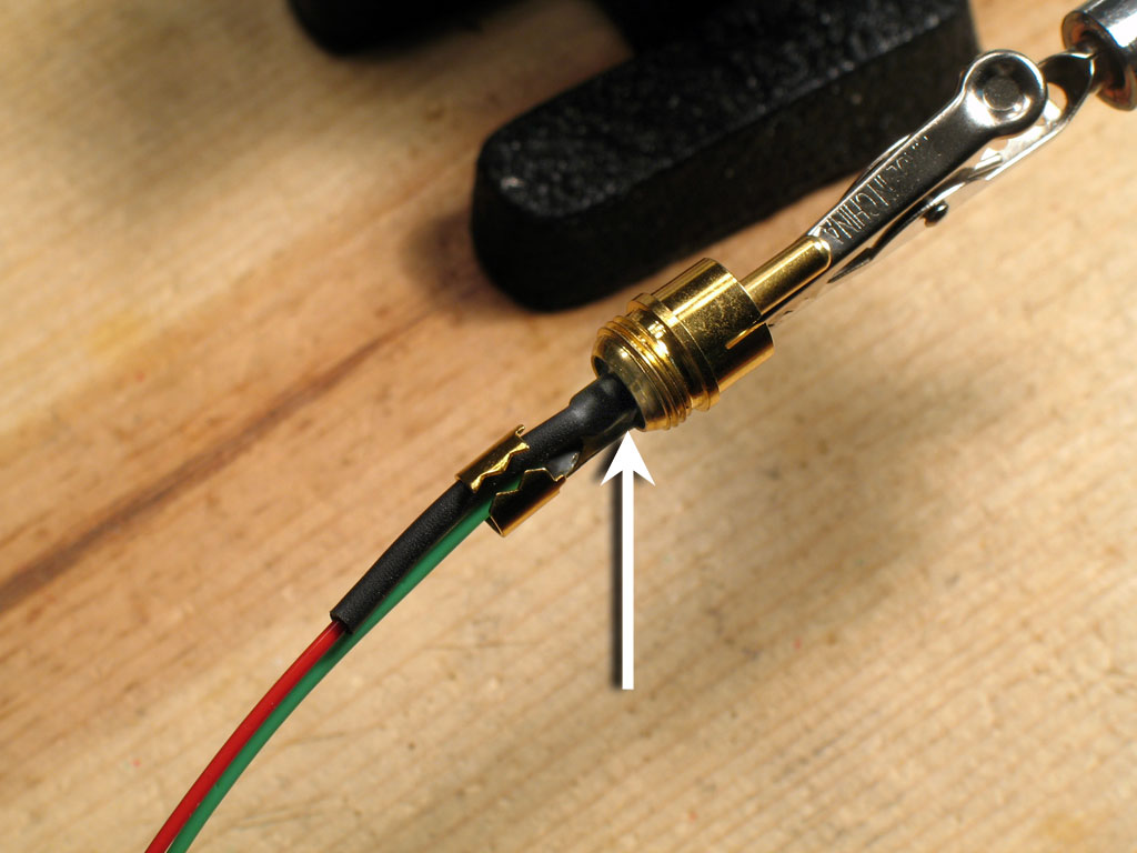
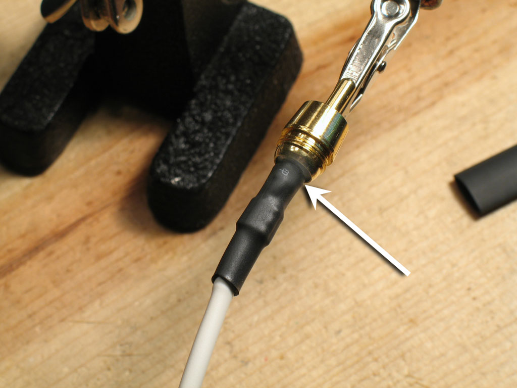
Next, take one of the 1/4" x 1-1/2" long heat shrink pieces, slide over the entire assemby, and shrink into place. Be sure to push as far forward as you can (white arrow), before shrinking into place.
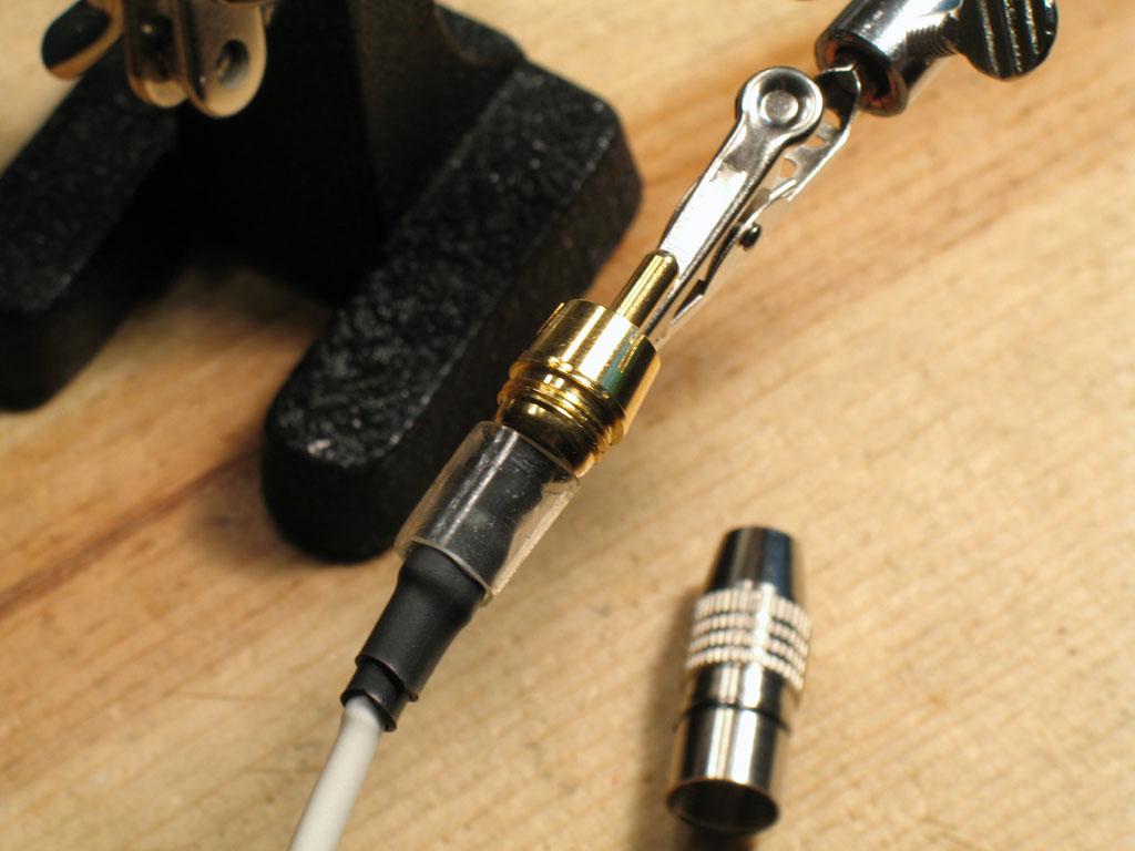
Finally, add one of the shorter pieces of the 1/4" heat shrink - 1" long - and shrink into place. What we're doing is building up the diameter of the lead assembly so that it fits better into the connector. Finish it off by sliding the clear gasket (comes inside the RCA plug) over the assembly.
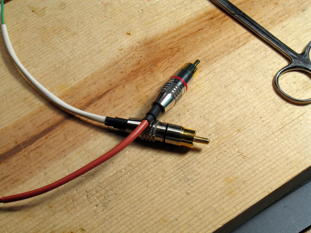
At this point, you can screw on the RCA plug body and shrink the remaining of the 6" heat shrink if you haven't already. Repeat this procedure for the other lead. Pictured below are the separate, finished RCA leads.
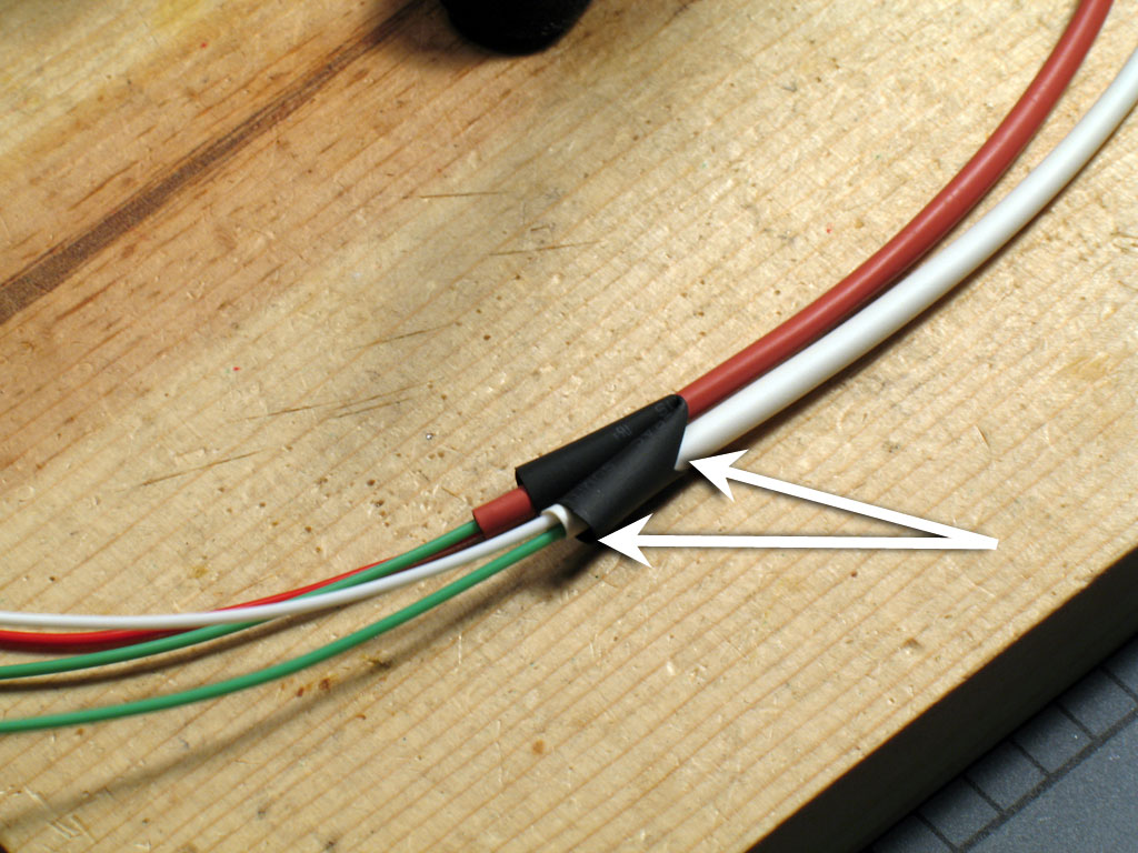
Now we want to combine the two separate leads into a single assembly for connecting to the grubDAC. We do this by using the heat shrink piece we cut that notch in earlier. Bend it in half at the notch and feed each lead assembly through one half of the heat shrink piece. Try to get the heat shrink close down to the end of the 6" heat shrink, but not onto the actual wires. Shrink into place.
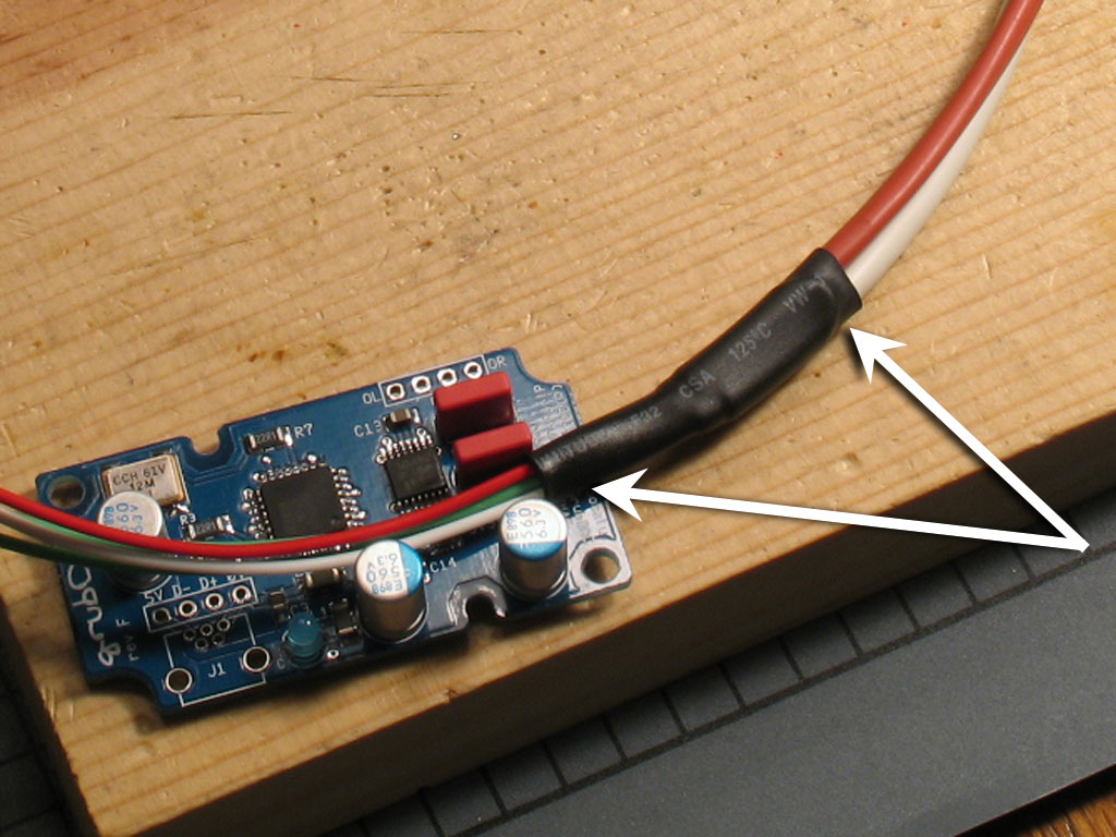
Finish it off by placing the last piece of 1/4" x 1-1/2" heat shrink over the V-connection. Run the 1/4" heat shrink up to and just over the edge of the V-connector on the RCA plug side. The remainder to the other side will be shrunk down over the actual wire leads. This will be the point where the leads will exit the grubDAC case. Refer to the 2nd pic below for this final heat shrink and the white arrows for details.
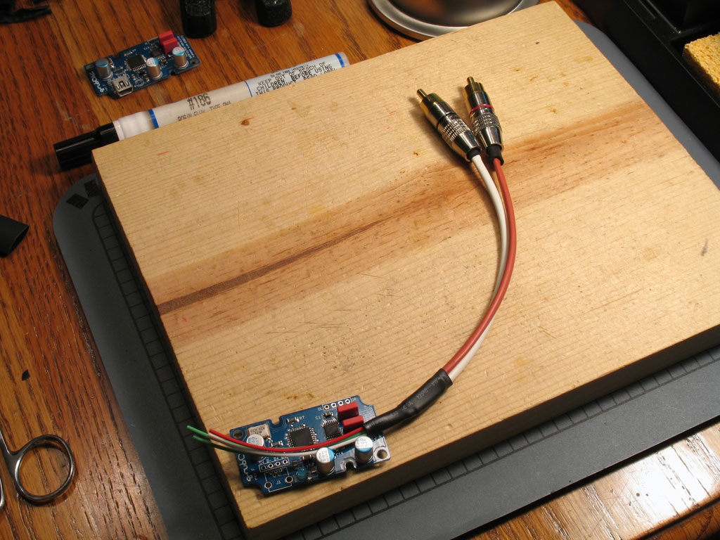
Now, it may look like we've got a lot of wire leads left over (3"?). However, the actual exit from the case is off-center and the output connections are all the way over to the side. We need that extra lead length to give us enough to curve the leads around as shown in the pic below.
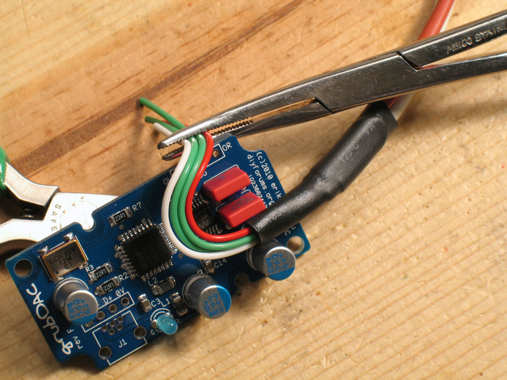
Now that we've got the wire curved around to the output pads, we need to make another twist and bend in different planes. In the piping industry, one would call this rolling the elbow.
(Note: I built two grubDAC's at the same time. This one has the LED soldered in place, but obviously, no mini-USB connector. |