Buy Boards & Parts:
www.beezar.com
DIYForums.org
The Mute Audio GrubDAC

GrubDAC Construction - Build by Photo 2

For soldering the SMD passives, the standard SMD manual soldering method applies:

  1. Apply a bit of solder to one of the pads.
  2. With the tweezers in the left hand, pick up the part so that you place it on the pads on the PCB.
  3. With the soldering iron in the right hand (I'm right handed, you can reverse this if you're not), melt the previously applied solder on the pad while placing the part on the pad.
  4. Go back and solder the other end/pad.
Some pointers on this -
  1. Apply flux with the flux pen to the pads you want to solder.
  2. Being right-handed, I apply solder to all of the right-side pads for the parts I'm going to solder.
  3. For parts that are oriented vertically on the PCB, apply solder to the bottom pad. That way, you can rotate the helping hands up so that the helping hands are on the left, and the soldered pad is on the right - allowing free access.
  4. Watch out for ground plane pads. Deviate from steps 1), 2), and 3) if needed.
  5. With through-hole soldering, it's best to do the smallest parts first. With SMD, though, it's better to do the inside parts first, then work outwards to the edges of the PCB. This gives you the best access.

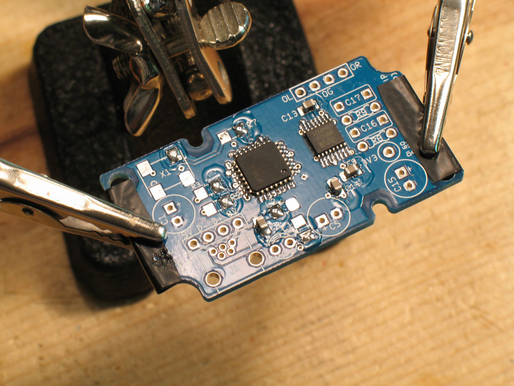
In the pic, you can see that I picked the smallest 805 capacitors that are mostly toward the center/inside of the PCB. The right pads have been soldered and then re-melted to place and anchor the small capacitors.


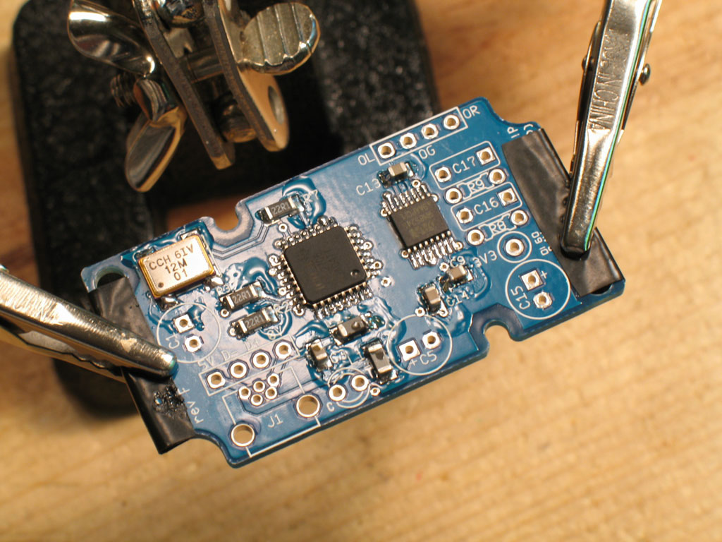
In this pic, I've soldered the left side of the 805 capacitors and added the 1206 resistors and ferrites. Next will be the oscillator.


The oscillator is shown soldered here. Like one of the IC chips, I anchored the top right point, first, then proceeded to solder the other four corners. Most of the pads on the oscillator are on the bottom, but there are small sections of copper on the sides. I try to make sure the solder is contacting that copper on the sides. I don't know if that's important, but I've built four so far and they all worked the first time out.


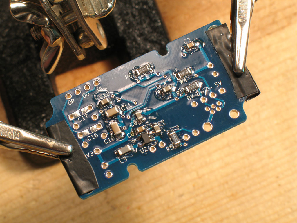
Next up is the back side of the PCB -
Here we need to solder the TPS regulator, first. It's a very small 5-pin IC chip, two pins on one side spread apart, then three pins on the other side that are close together. I deviate a little from the SMD soldering strategy with this chip and anchor the center pin on the side with the three pins (at the arrow). This gets the hardest pin out of the way first, because you can come at the other pins from any corner unobstructed. These pins get soldered individually. The only problem I've ever had is that it seems these chips are more susceptible to SMD Tiddly Winks than any other. I've shot several across the room with my tweezers, never to be found again. So, be careful!


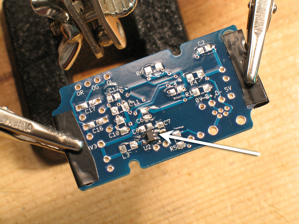
Now that we have the TPS chip soldered, all the rest of the parts on the bottom are simple passives. As described before, I flux all the pads, then place solder on either the right-hand pads or bottom pads, depending on whether the part is horizontal or vertical. The arrows illustrate this strategy at a couple of positions.


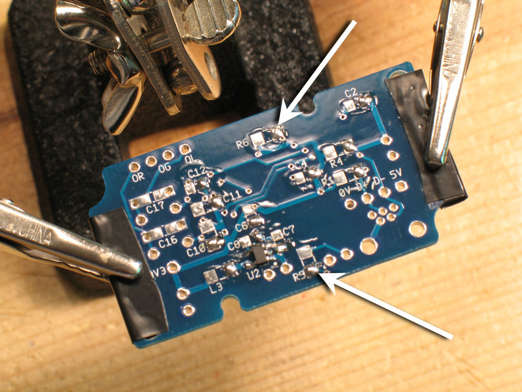
As before on the top side, here we see all the small 805 capacitors soldered.


Next up are the 1206 parts. This goes very fast when you use the flux/right & bottom/solder-to-the-pad technique.


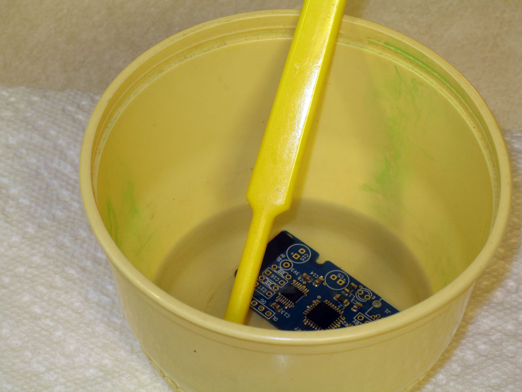
Now we're done with the SMD parts! Since all of the SMD parts are sealed, I like to immerse the entire PCB in the good old 91% alcohol. This gets things cleaned very fast.


You may still need to touch up with the toothbrush and pat dry with a paper towel. The paper towel will help to soak up the flux that the alcohol has dissolved.

 
file last changed:Thursday, July 1, 2010 7:00:00 AM
Please contact the GrubDAC webmaster for questions about these web pages.