www.beezar.com

|
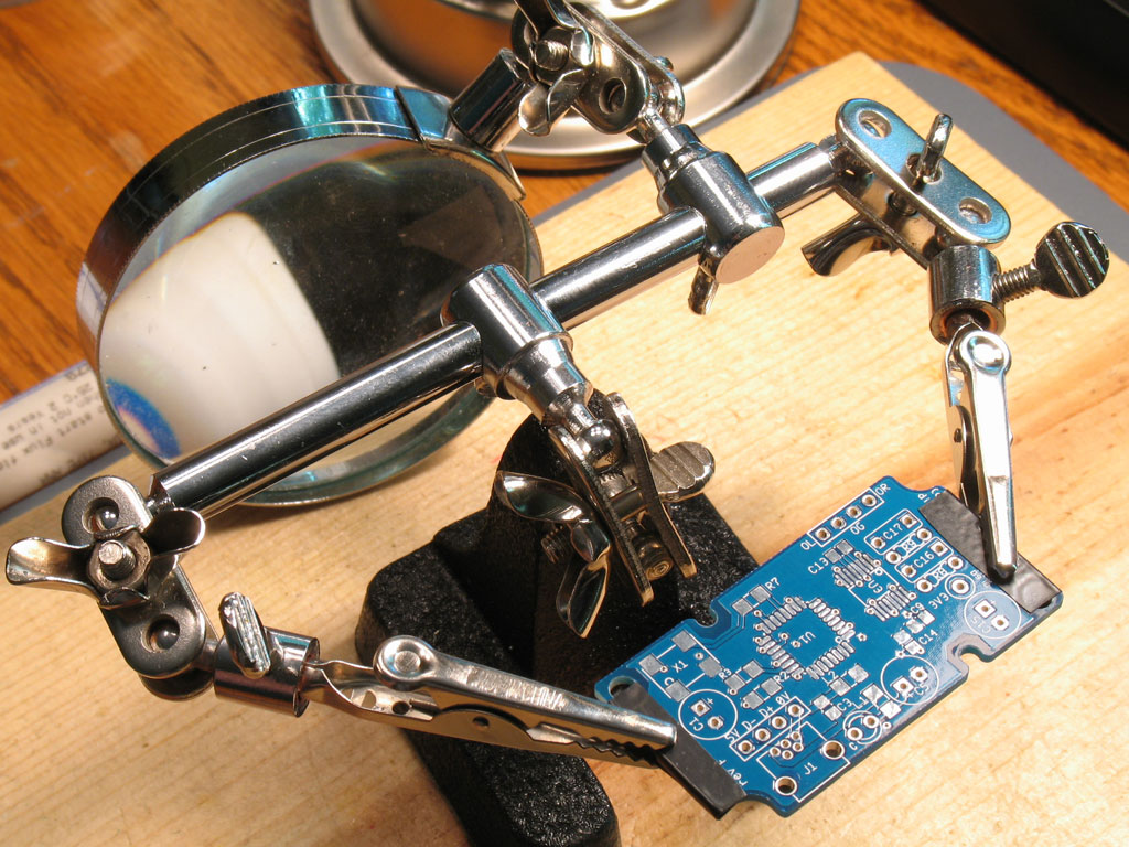
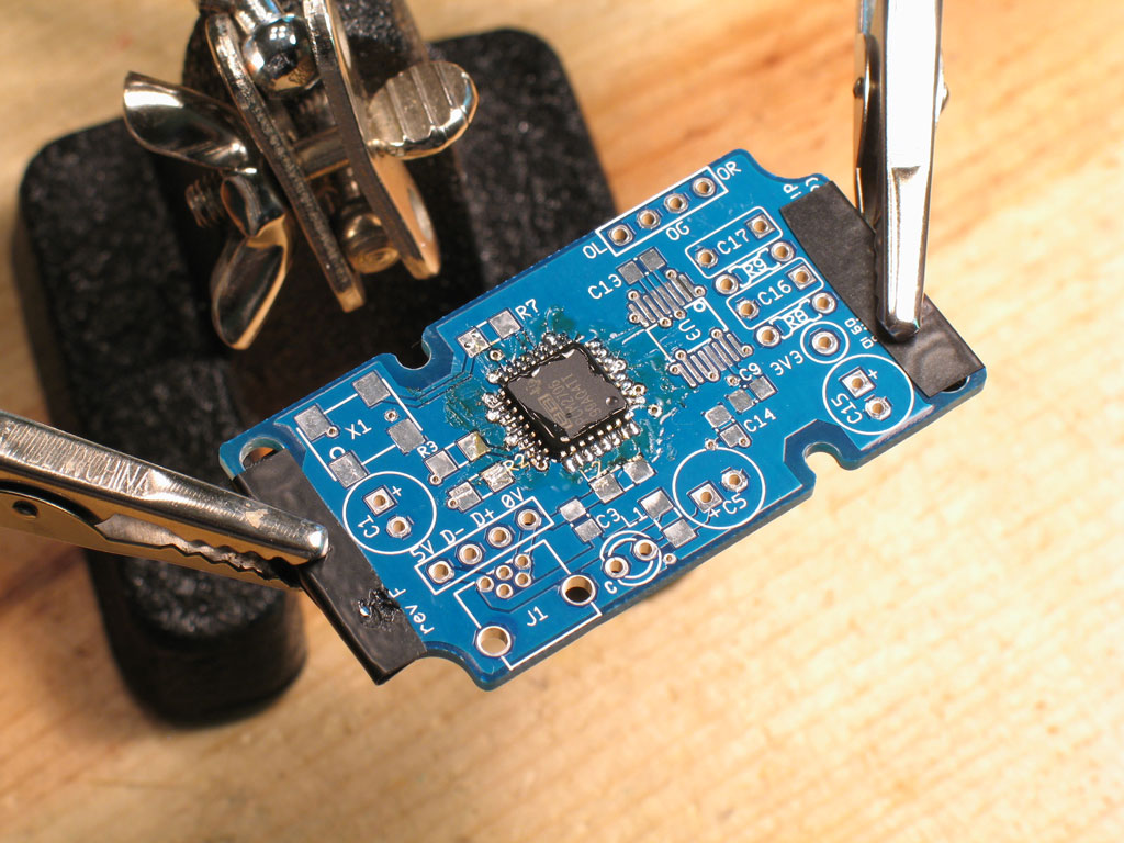
Here we have the grubDAC PCB all set up in a cheap pair of helping hands ($1.99 atHarbor Freight). A couple of small strips of electrical tape cover the ends of the board, on top and bottom, to keep the alligator clips from scratching the PCB. I know many of you think these helping hands are worthless, but with a little care, they will do the job.
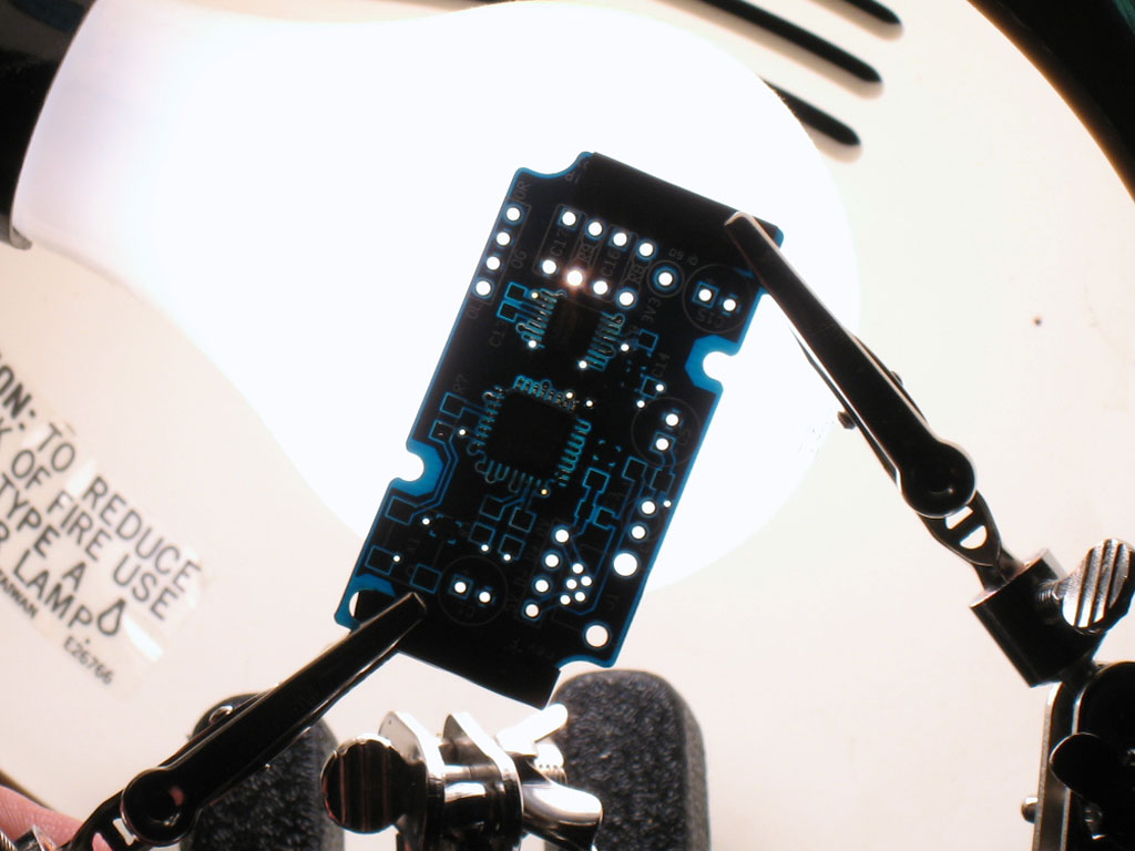
This pic illustrates what I mean. Using the magnifying glass as a counter-balance, it should be possible to set up the helping hands so that the grubDAC PCB is level and will actually support weight without collapsing. This will let you apply the needed pressure when soldering without having the whole thing collapse on you. Properly set up, the helping hands should never fall during the entire time you're soldering the PCB.
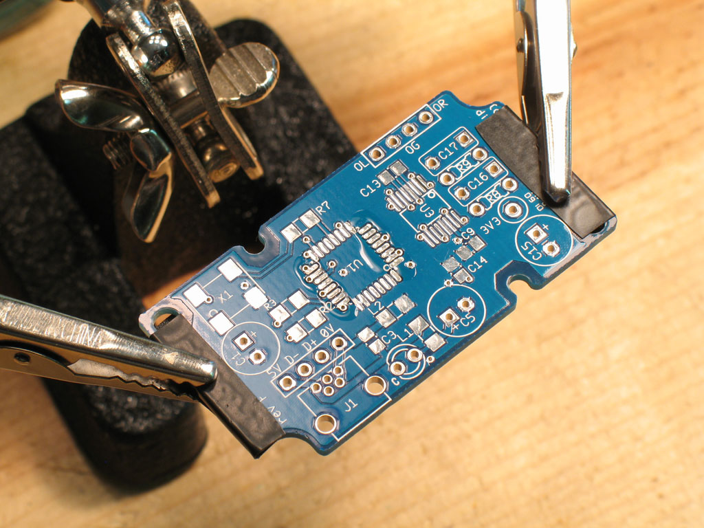
For the first step, we want to solder the PCM2706/7 chip. That's because you need to be able to reach it to solder on all four sides of the chip. That makes it the first candidate to solder, over anything else that might get in the way. In the pic, you should be able to make out the flux pen flux on the left and right side of pads - those are the ones we'll solder first.
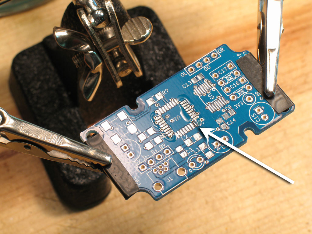
The standard technique for soldering SMD is to apply solder to a single pad. Then with the tweezers holding the part in one hand, melt the already applied solder on the pad with the soldering iron in your right hand. While the solder is melted and you continue to hold the soldering iron in place, move the part into position on that pad. When the part is straight, remove the soldering iron and let the solder cool. The part should be anchored in place, ready for final soldering of the other pads. This is common for all SMD parts, even the multi-pin IC chips. Here we see a small bit of solder applied to the right-most bottom pads for the PCM chip. I picked this pad for a couple of reasons - 1) it's not attached to the ground plane (those are harder to solder and not good choices for an anchor), and 2) we'll be soldering the right and left side pads first, so this one won't get touched until two entire sides of the chip are soldered.
A small caveat to that is that the large chips will still move with only one corner anchored, so here we see that I also tack-soldered the left-most top pad, too. Now the chip is anchored with two opposite corner pins and will not move while we solder the left and right sides.
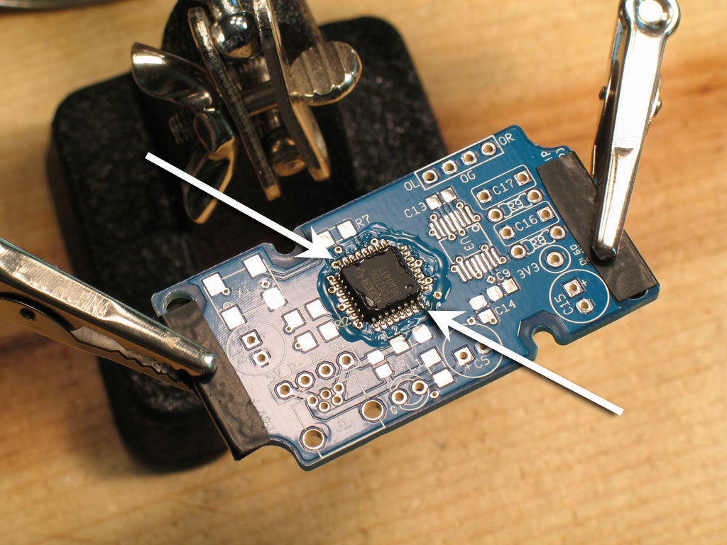
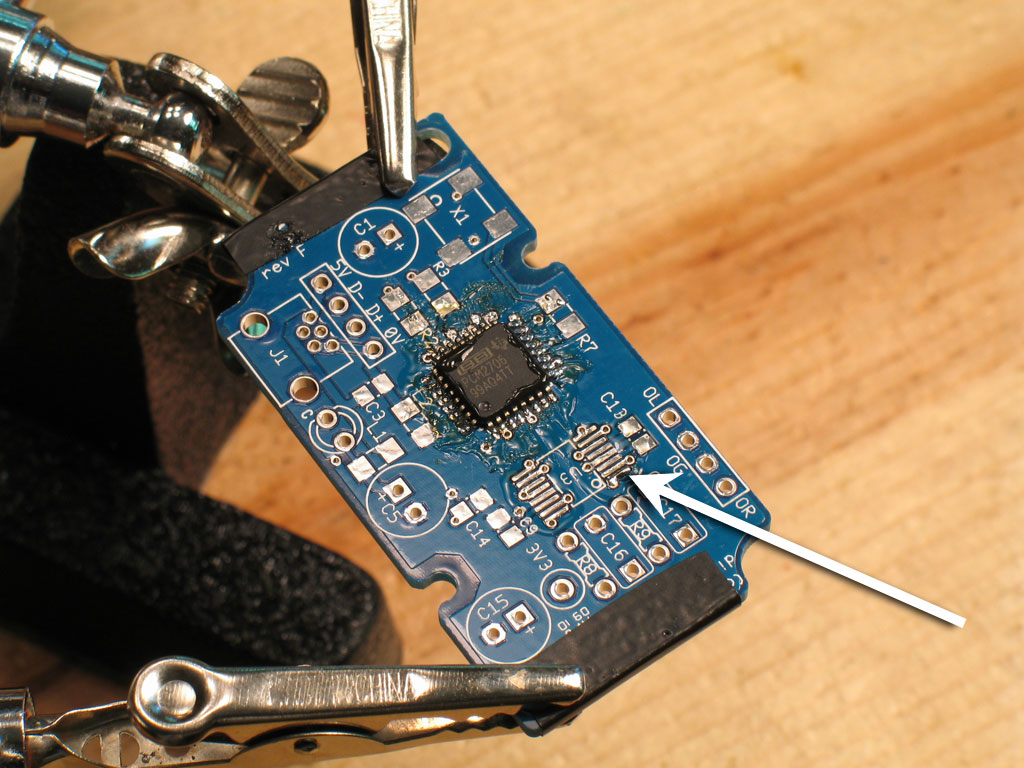
Here we see all four sides soldered. I won't go into the details of soldering SMD IC chip pins - you can refer to the GrubDAC or BantamDAC websites, or the Tangent tutorial referenced earlier. Suffice to say that for the chips used on the grubDAC, it's possible to solder individual pins with the solder and tip I specified earlier. That sort of makes it a lot easier than down-and-wipe, flood-and-suck, etc. I still cheat, though, and go against all the norms of soldering.;-) I apply a tiny bit of solder to the tip of the iron, then touch it to each pin, repeating as necessary. It works fine. :-) Use more flux as necessary - it burns off fast. For the top and bottom sides, I simply rotated the helping hands. Note however, that some of the electrical tape got melted doing that. This is because even though I was almost soldering pins individually, I was still holding the iron horizontal and using the down-and-wipe method to finish off the solder on the pins.
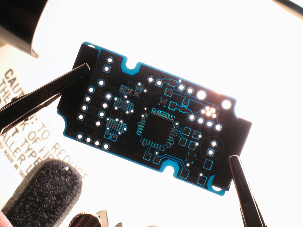
A quick check against the light bulb to see if there are any bridges -
Next up is the Wolfson chip! For this one, I re-position the alligator clips and helping hands to get the PCB as near-vertical as possible. That way, I'll have an unobstructed soldering path for the pins:
Here we see flux applied to the both rows of pins, with solder applied to an anchor pad at the bottom right:
Both rows of pins have been soldered in this pic. Note that I continued with the anchor pins at opposite corners and soldered the top left pin before I began to solder the rest of the pins. Down-and-wipe finished off the pins for a smoother appearance.
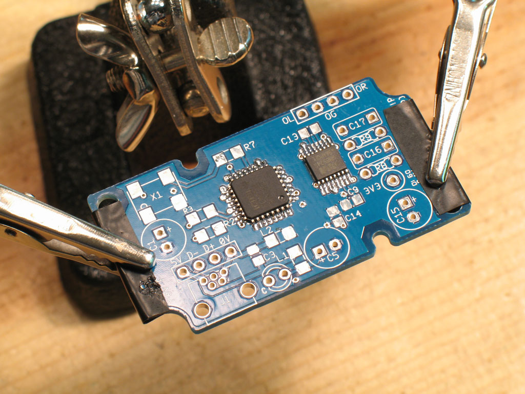
At this point, I clean the PCB of residual flux. Some 91% isopropyl alcohol and an old toothbrush work fine. This way, a clean PCB lets you do a better inspection of the soldering job and to spot errors. A final check against the light bulb for bridges and we're done with the IC chips!
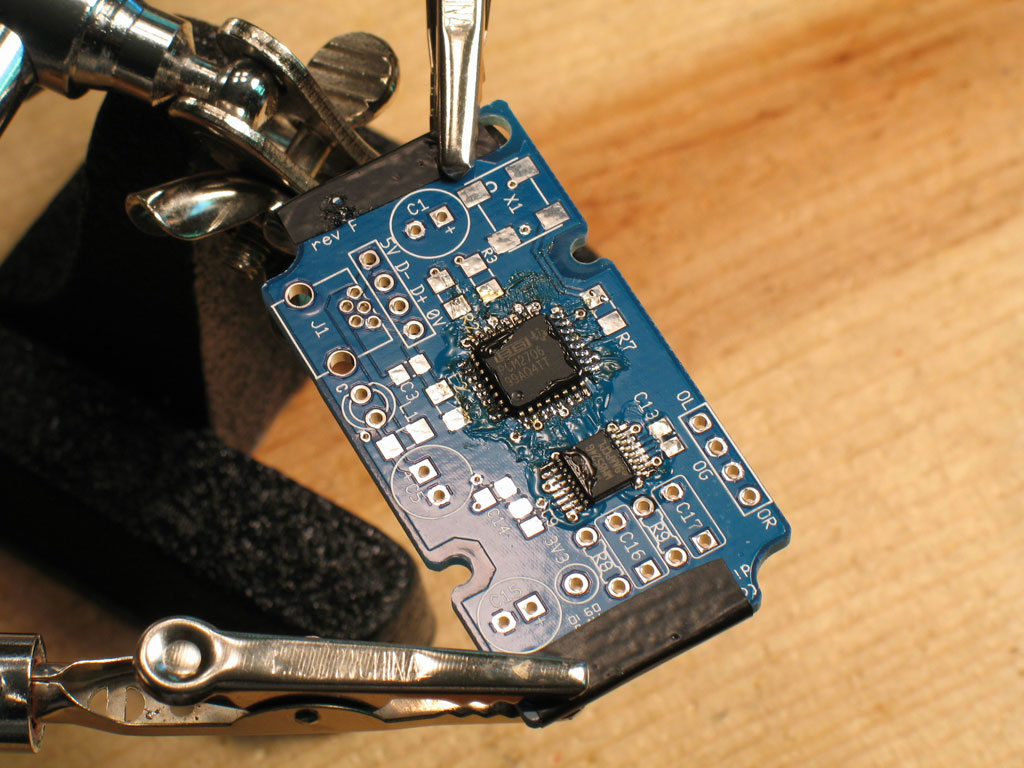
Here we see the PCB, all clean, both IC chips soldered and ready for the rest. More on the next page ... |