www.beezar.com

|
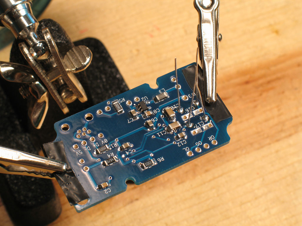
Next up are the through-hole parts. As with any PCB and through-hole parts, it's best to do the shortest parts first. Here we see the V-D CM50 resistors in their positions. You'll want to solder on the backside, allowing the solder to wick back up to the top. The holes in the PCB are pretty large compared to the resistor leads. This was to allow compatibility with other resistors, if you want. However, in the case of the CM50's, it may be better to cheat a little bit and tack-solder them on top at first.
Here we see the bottom side where I've applied solder to the leads/pads after tack-soldering the resistors in place on top.
... and a look at the resistors completely soldered. There may be a bit too much wicking go on there, but I wanted to make certain the joints were good through-and-through despite tack-soldering them on top at first.
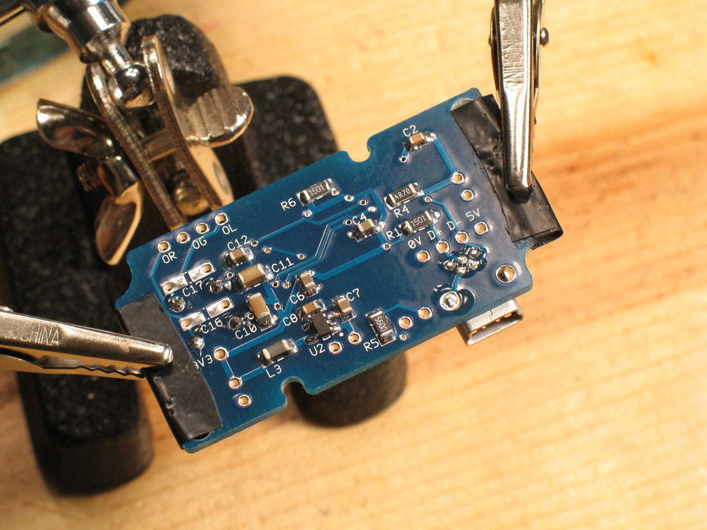
On this PCB, I'm soldering the mini-USB connector (as opposed to a CableDAC). It's pretty simple and the mechanical tabs pretty much keep it in place while you solder everything on the back. Remember that the tabs form a mechanical joint, though, so be sure that you fill those holes completely with solder. This will help things last through all of those multiple connections/disconnections with a mini-USB cable.
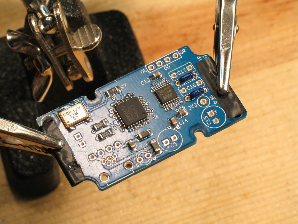
Next comes the Wima box capacitors -
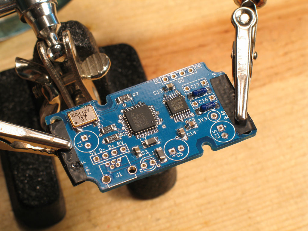
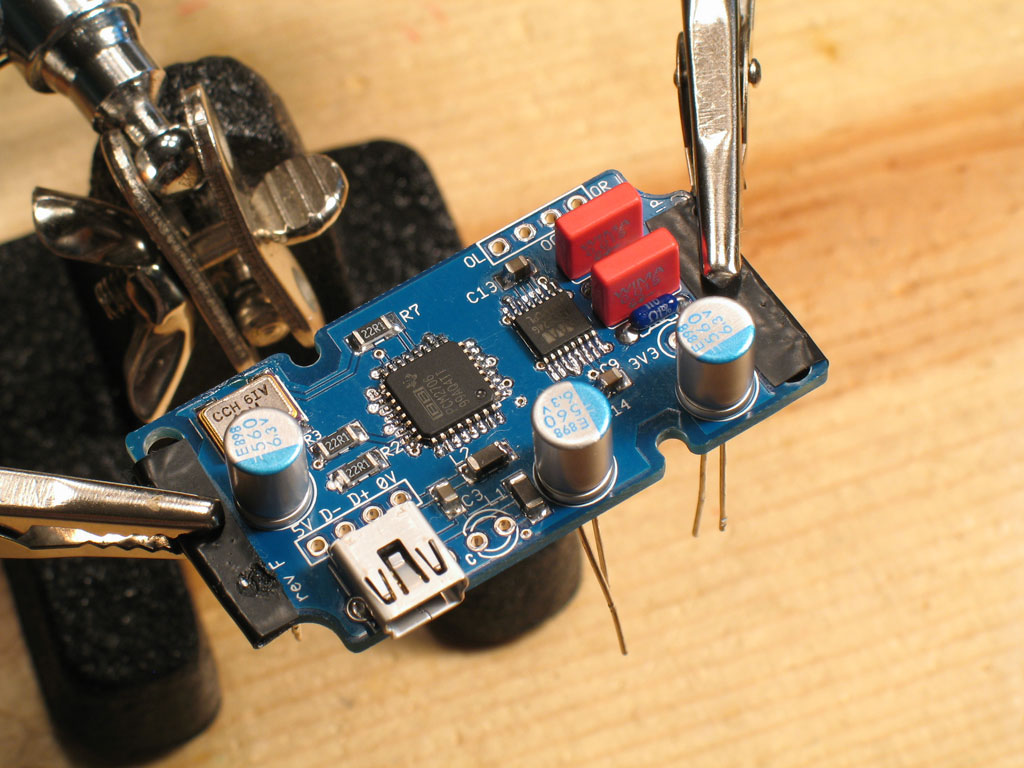
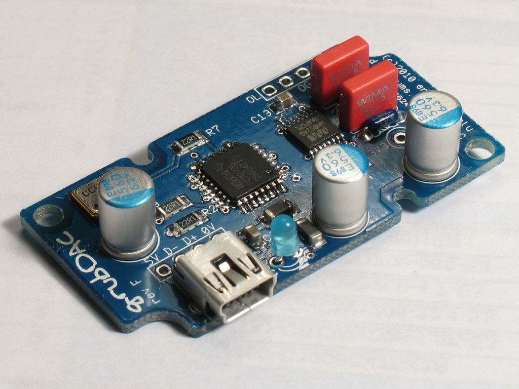
... and finally, the three electrolytics go in -
Here's the finished grubDAC, ready for casing and connecting to your favorite amp! (Note - I'm going to use this one on the MOSFET-MAX, but the LED goes on the front panel. I placed it in the holes, un-soldered, in this pic to give you an idea of what the finished DAC looks like.) Next page - detailed build-by-photo instructions on finishing a grubDAC for a CableDAC!! |