How to Build the Hybrid Headphone Amp
Updated October 28, 2005 for the latest PCB versionYou should have a copy of the schematic handy so that you can see why the parts go
where they go. It's not absolutely necessary, but it sure makes things go easier if you
get confused!
The build philosophy here is to work from the bottom up - short parts first, tall parts last.
The pictures below are from my Millett Hybrid that is installed "crosswise" in a Hammond
1455R1601 case. Also, the power LEDs in this amplifier are installed under the tube
sockets as AMB suggested in the forums.
Step 1.
Install the resistors and diode
RLED, R2L/R, R3L/R, R4L/R, R5L/R, R6L/R, D1, D2L/R
Remember, D2L/R is either a 1N5291 or J503 but NOT both.
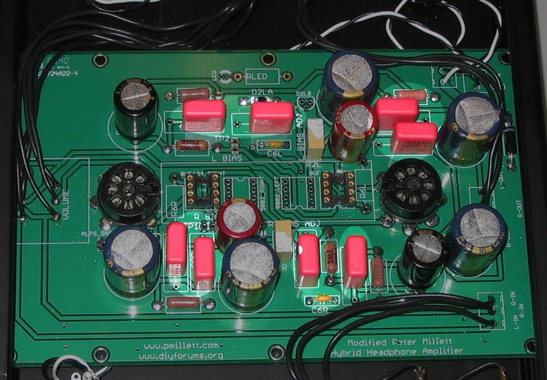
Step 2.
Install the buffer sockets

You must be sure to use the correct buffer in the correct socket! The two outermost
sockets are for the BUF634 or OPA551. The two innermost sockets are for the
Intersil HA3-5002. They are not pin compatible! Look at the board labeling
if you are unsure - each socket location is labeled with the buffer that it supports.
If you plan on using an OPA551, solder a jumper wire between pins 2 and 6 on the
underside of the board. It will have no effect on the BUF634 performance.
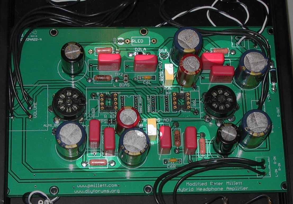
Step 3.
Install the fuse and the polypropylene and ceramic resistors
PF1, C3L/R, C4L/R, C5L/R, C6L/R, C8L/R
Step 4.
Install the tube sockets

VT1, VT2
Step 5.
Install the electrolytic capacitors
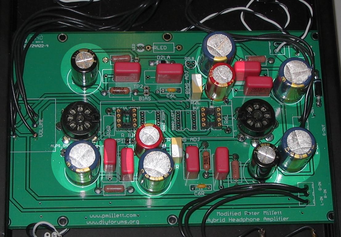
C1, C2R/L, C7R/L, C9R/L, C10R/L
Step 6.
Install the potentiometer and wiring.
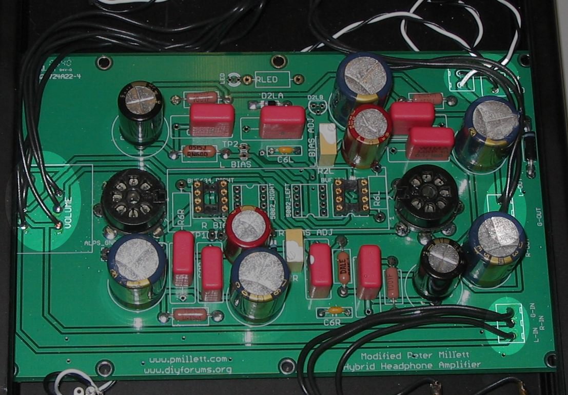
The board is configured for the Panasonic EV-J or ALPS RK27. You can also
use an off-board pot by wiring directly to the RK27 pot pads as shown in the picture
above.
What's left?
So at this point, the board is complete. You'll need to put it in a box, connect the
input and outputs, the power and the switch wires and the LED.
And, of course, a couple of tubes.
Once that's done, power it up and grab your voltmeter. Using the left and right bias
test points, adjust the bias resistors (R5R/L) to around 12VDC (with a 24V power supply).
Fine tune the bias by ear (if you can hear the difference). Once you've set the bias, dab
a little nail polish or white glue on the bias resistors so that they will not drift.
!!!!!BEFORE YOU PLUG IN YOUR HEADPHONES!!!!!
Check the output of the headphone jack (right to ground and left to ground) to make sure
that there is no DC on the output. A few millivolts is OK - what you're checking is to make
sure that the output coupling caps are doing their job blocking the 12V of DC offset from
the tubes' plates.
!!!!WARNING!!!!
One of the "features" of a single power supply and large output coupling caps is that
when you turn your amplifier on and off, the output will be unstable for a few seconds. That
means anything from some noise to some DC offset that is not blocked by the output caps.
Do yourself and your headphones a favor: unplug your cans before you turn the amplifier
on or off.
OK - that's it - plug 'em in and enjoy!
Home