Buy Kits & Parts:
www.beezar.com
www.beezar.com

The ECP Audio
T
O R P E D O
| III |
differential hybrid parafeed headphone amplifier
| |
Tweak #5: Output CCS (Constant Current Supply for the Differential Buffer)
ECP Audio designed Constant Current Supplies (CCS) for the differential output buffer of the Torpedo III. They are meant to take the place of resistors R19, R20, R21, and R22. They provide improved performance for the overall amplifier circuit. The effect can be compared to increasing the bias on a Class A amplifier circuit: more current, more heat, but greater bass authority and improved micro-detail resolution. This is one of the most significant tweaks you can install for the Torpedo III. However, pleaser remember that these Output CCS boards are installed directly into the high-voltage portion of the amplifier circuit. Standing vertically in the correct positions, they present a major shock hazard if you touch any part of these boards when the amplifier is powered on. We recommend that all safety procedures are in place before powering the amplifier up - in this circumstance or any other. That means the lid should be on the amp, and the safety ground should be connected. Please observe these precautions when installing and testing these boards.
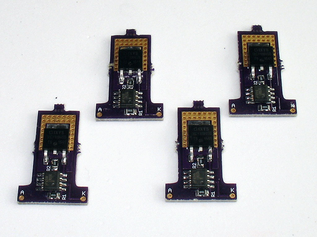
Because of the nature of the surface-mount design, these are only available in finished/tested form and in quads from beezar.com. (Four boards are required per Torpedo III.) Simply install them vertically, flush on the resistor pads for R19, R20, R21, and R22. R19, R20, R21, and R22 must be removed! They must be installed vertically, with the bottoms flush to the Torpedo III PCB. Use spent resistor leads soldered into the "K" and "A" pads. Note that two Output CCS boards will face backwards and two will face forwards. This is because the "A" pad must be connected to the respective resistor pad that is closest to the heat-sinked transistor nearby. Finally, finish up the installation by installing some Dow Corning 748 at the junction of the Output CCS boards and the Torpedo III PCB. The following diagram and photos explain this installation. Here is a partial diagram of the Torpedo III PCB indicating the locations and orientation of "A" and "K" for the Output CCS boards: 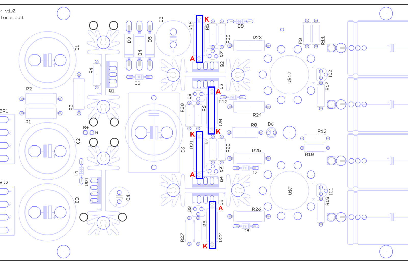
Install the boards by using spent resistor leads in the "K" and "A" pads. You should be able to "hook" the lead around to both sides of a CCS board so that you have one long portion pointing down (just like any other through hole part) and one shorter end of the lead bent down on the other side. Trim the short end of the other side so that it does not poke down farther than the bottom edge of the Output CCS board. This way, you can insert the long lead portion of "K" and "A" into the resistor pads on the Torpedo III PCB. On the left, you see the Output CCS board with the long leads at "K" and "A". On the right, you see the shorter, hooked-around leads at the bottom edge of the Output CCS board. The "hooking around" is a small thing, really, but adds better vertical stability to the board when installed on the Torpedo III PCB. 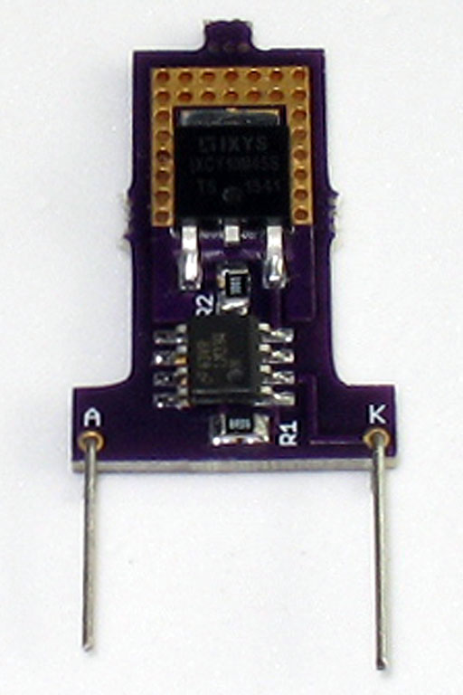 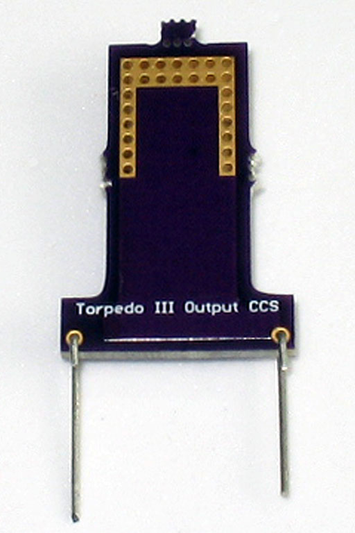
Here we see the leads soldered in place. Try to get them as perpendicular as you can. If you have trouble, a little bending is OK, but you want them straight and the distance between the leads should be consistent with the distance between the "K" and "A" pads. This will aid you in placing them into the resistor pads on the Torpedo III PCB. On the left, you see the Output CCS board with the long leads at "K" and "A". On the right, you see the shorter, hooked-around leads soldered and trimmed above the bottom edge of the Output CCS board.  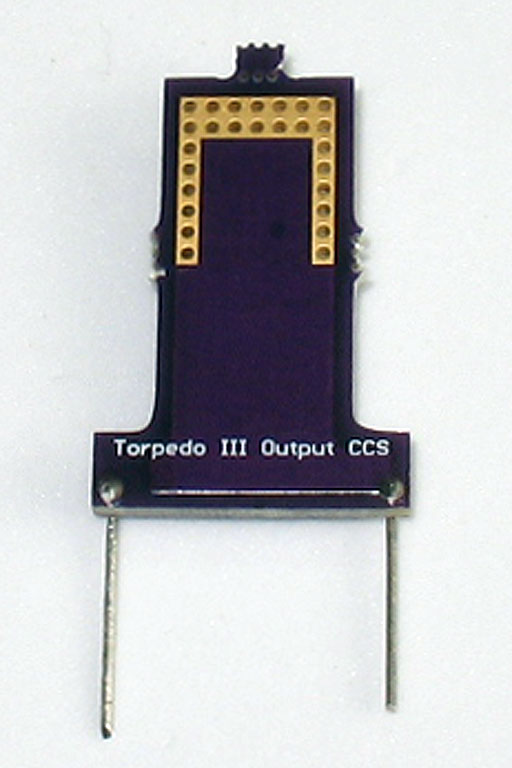
Here are pics of the Output CCS boards installed. You can see the Dow Corning 748 also applied. It's not pretty, but will add some strength and stability to the boards. 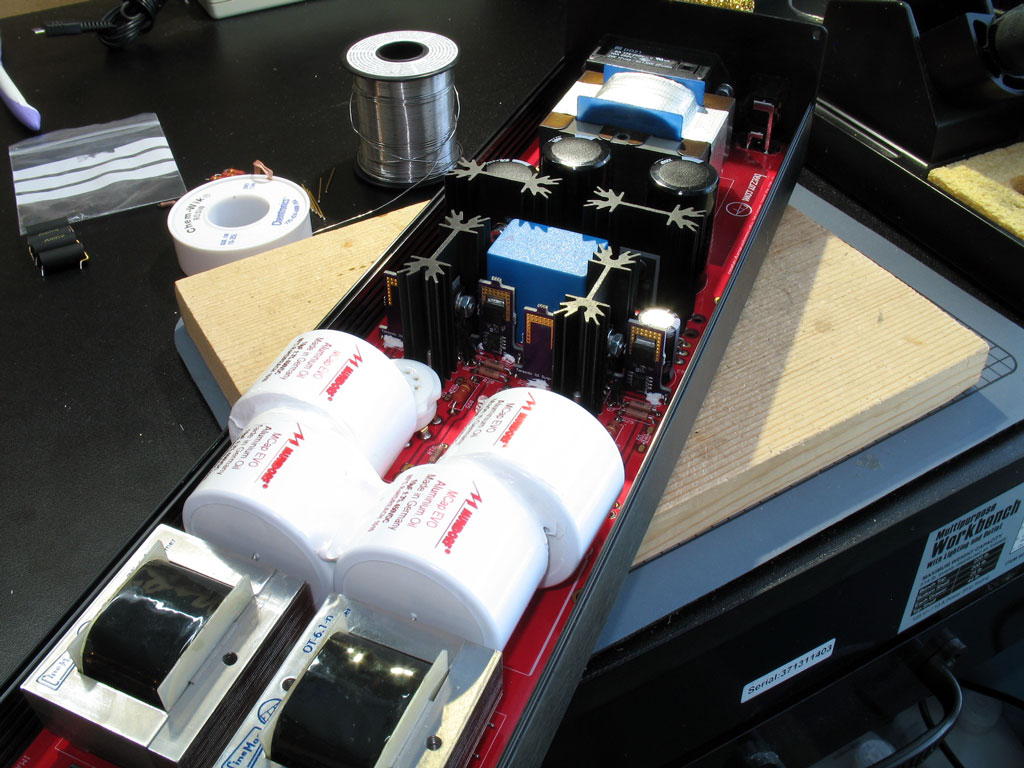

Note: these PCBs are broken apart into tiny individual PCBs from the manufacturer. As a result, there are sprues/flashing sticking out in the middle of all four sides of the tiny boards. These will not affect the function. Neither will they get in the way if you solder them flush on the bottom of the PCB as recommended. Note that Beezar has sanded the bottom edge flush already. If you're a stickler for appearances, however, feel free to sand the sprues away flush on other edges of the boards. |
file last changed:Friday, August 5, 2016 8:27:07 AM
Please contact the TORPEDO III webmaster for questions about these web pages.
