www.beezar.com

The ECP Audio
T
O R P E D O
| III |
differential hybrid parafeed headphone amplifier
| |
 |
|
From Dsavitsk: "Caps should be at least 300V with min 10uF recommended. Sims with caps as small as 1u show that they transfer bass frequencies, but the phase is distorted which will make it sound like they don't. You might do OK with slightly smaller (8u? possibly 5u?) but I wouldn't really recommend it. You might also be able to parallel 2x 5u caps or something. You can also try a bypass, though I have not tried it. That said, there are pins for 27.5mm, 32.5mm, 37.5mm, 45mm, and 53mm. Width is the bigger issue 21mm width/diameter being the max. There is actually very little out there that will fit as most things are a little too fat. And don't use anything with a conductive exterior as it will cause a short." |
||||
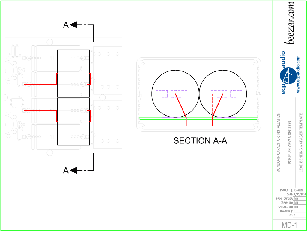
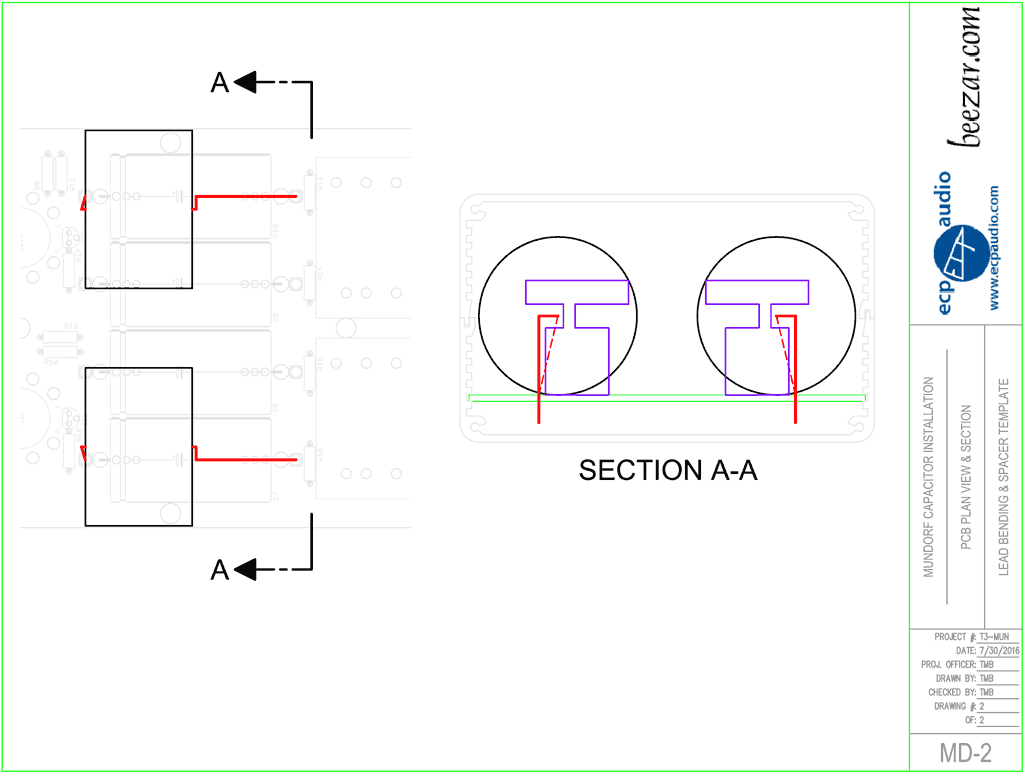
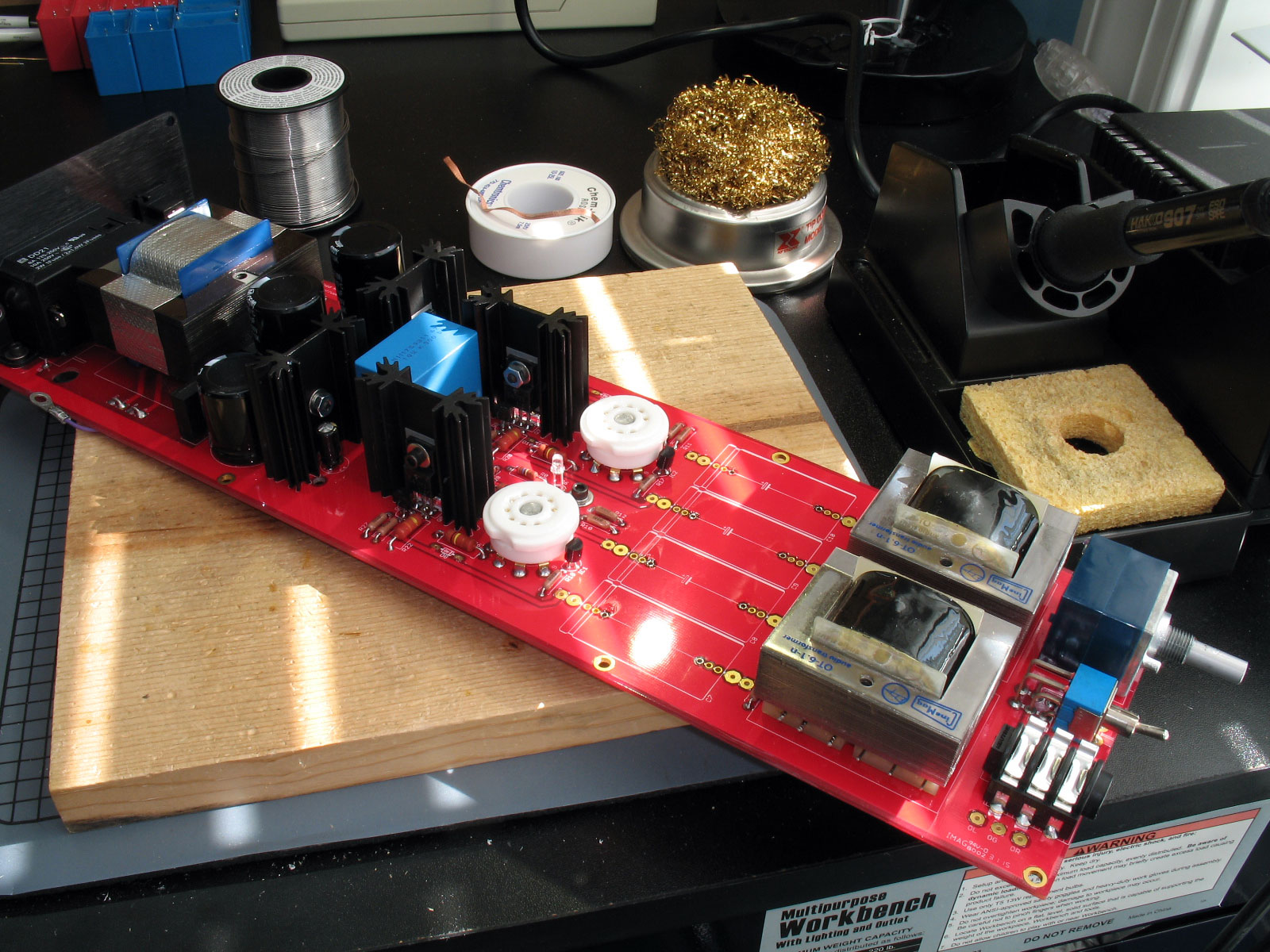
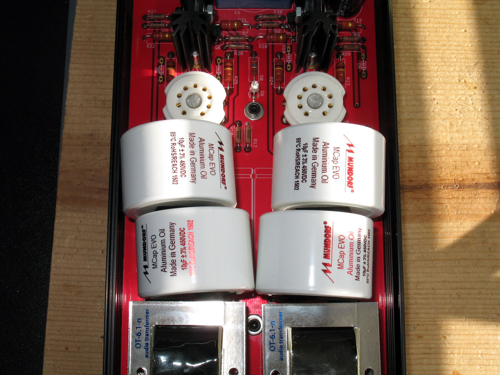
| Note: Due to some very enterprising Torpedo III builders, (Fierce Freak, Mister Rogers and Dr. Findley on SuperBestAudioFriends.org), it was discovered that the new line of Mundorf film caps - the EVO series - will fit on the Torpedo III if some special techniques are used. The Mundorf film caps that are recommended are the Mundorf EVO Aluminum-Oil film capacitors. (The Mundorf Silver-Gold-Oil caps will fit as well, but those will set you back a few hundred dollars.) To be specific, the recommended parafeed caps in this tutorial are: Mundorf M-Cap EVO Aluminum.Oil, 10uf 450V, 40mm diameter, 27mm long The following description details how to succesfully install these capacitors in the Torpedo III. Other methods may work. This procedure is not exclusive at all. If what you come up with works and is safe, then by all means, use your method. The primary limitation is that the caps are 40mm in diameter and 27mm long. The spacing for the parafeed caps on the Torpedo III is approximately 53mm between the two farthest pads on the PCB and the PCB width clearance inside the case is approximately 99mm. This means that you must install the caps so that there are two rows and you must figure out a way to get 54mm (2 x 27mm) plus some leads' thickness into the 53mm space (the caps will hang over slightly in the lengthwise dimension). |
||||
|
***NEW*** Lead-Bending Templates ***NEW***
|
||||
| The key to installing the Mundorf EVO caps is in bending the leads properly. Two rows of capacitors with two leads each must somehow connect into only two rows of pads on the PCB. The following are some templates that are useful as a guide in bending the leads on the capacitors. However, it should be emphasized that regardless of how carefully you bend the leads, the bend corners and lead thickness will mean that some trial and error fit will always be necessary. | ||||
 |
| |||
 |
| |||
|
***NEW*** Mundorf Capacitor Installation Instructions! ***NEW***
|
||||
|
Please note that the procedure for installing the Mundorf caps has changed!!
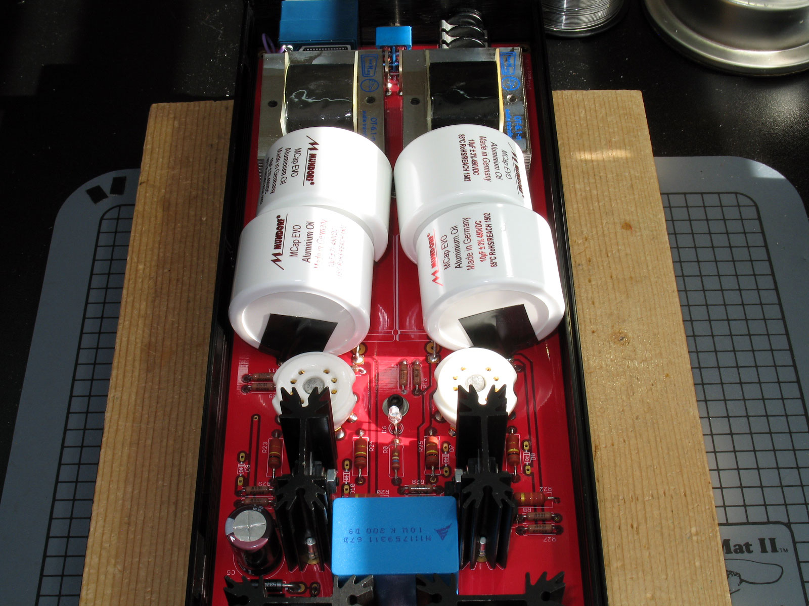
Two spacers are now included in all kits and all assembled T3s. The spacers are intended to ensure that the cap leads in the middle, between the front row of Mundorf caps and the rear row of Mundorf caps, never touch each other. The space between the two rows of caps represents a point where over 200V exists. If the leads touch here, disaster will result. The spacer, when properly installed, will ensure that this never happens. In addition, we highly recommend the use of Dow Corning #748 as a caulk/glue between the two rows of caps. (Additional caulk between the caps and PCB is also recommended, but not absolutely critical.) Here is a pic of the Dow Corning applied to a T3: 
Except for this change and a slight change in bending the leads where the spacers are placed, the information below is still a good guide. | ||||
|
Photo instructions, step-by-step
|
||||
|
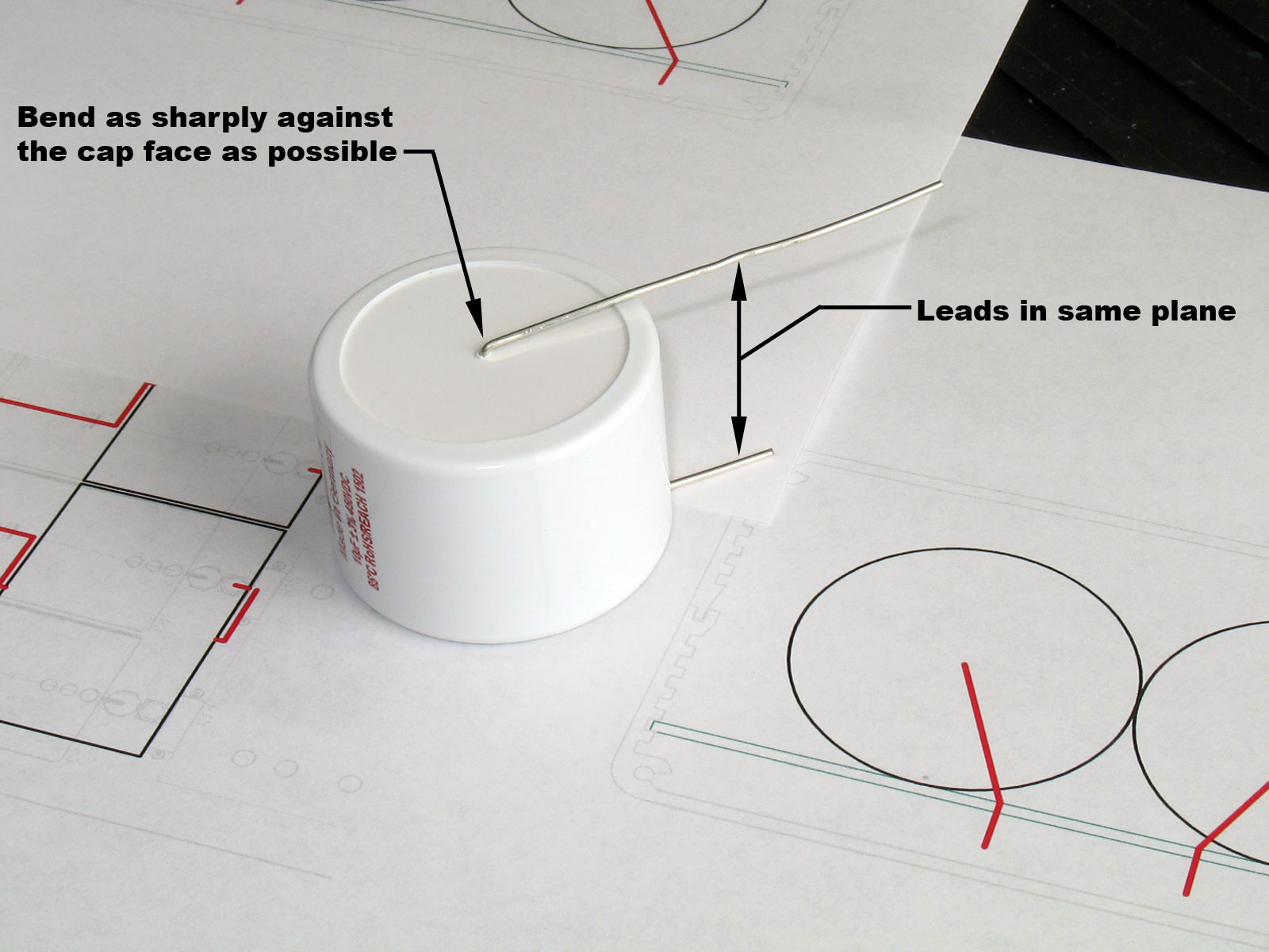
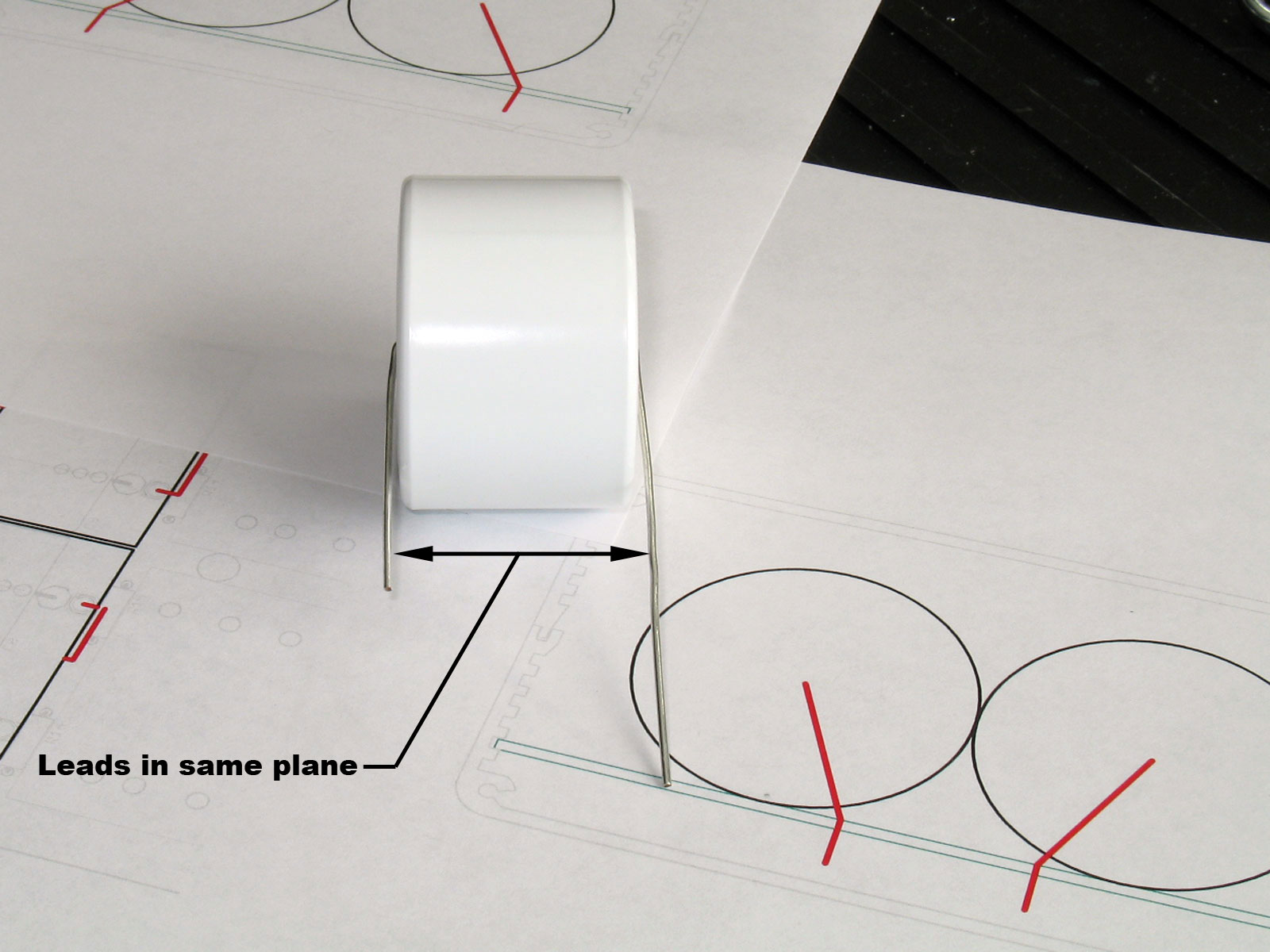
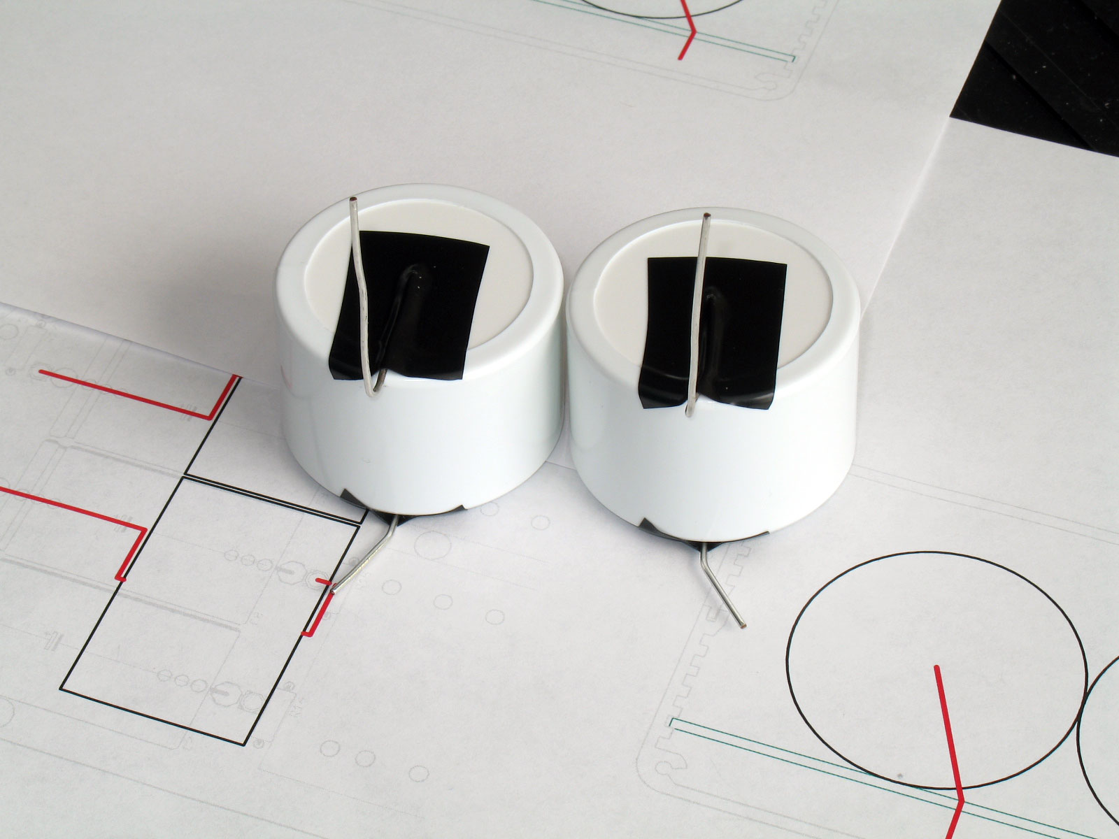
Print out the templates, straighten the leads (some suppliers seem to like to smash them in all directions) with as few bends/bumps as possible. Keep in mind that the leads are very ductile, but they will snap if flexed back and forth too much. Also, make sure you bend the leads down across the face of the cap as tight as you can and both leads need to be bent down in the same plane.
Warning: Do not twist the leads like hands on a clock face. If you need to change directions, straighten them back out and the bend them again. If you twist the leads like the hands on a clock face, you can tear them away from the dielectric on the inside. Another view of the first bend in the leads: After bending the leads on all four caps, I used electrical tape to both hold the leads down and to also provide insulation. Normally, I always use heat-shrink and never use electrical tape. However, good quality electrical tape has a dielectric strength to 600V and temperature resistance is good to 80 deg.C., about the same as the Mundorf capacitors. In any event, the electrical tape ensures that you will save the most space front to back as you stack the caps into the T3:
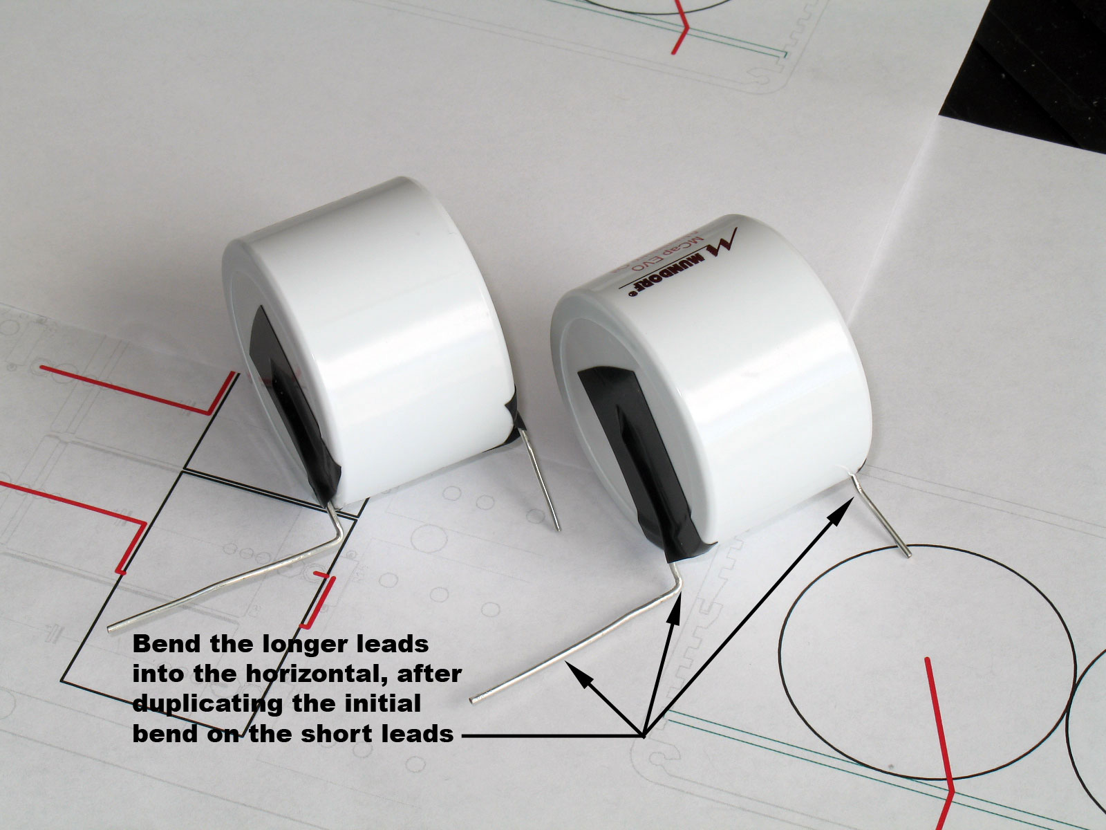
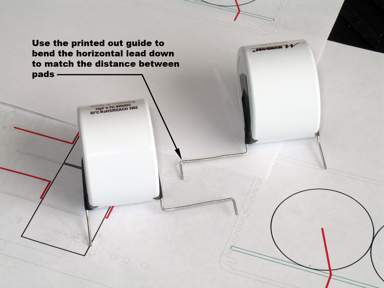
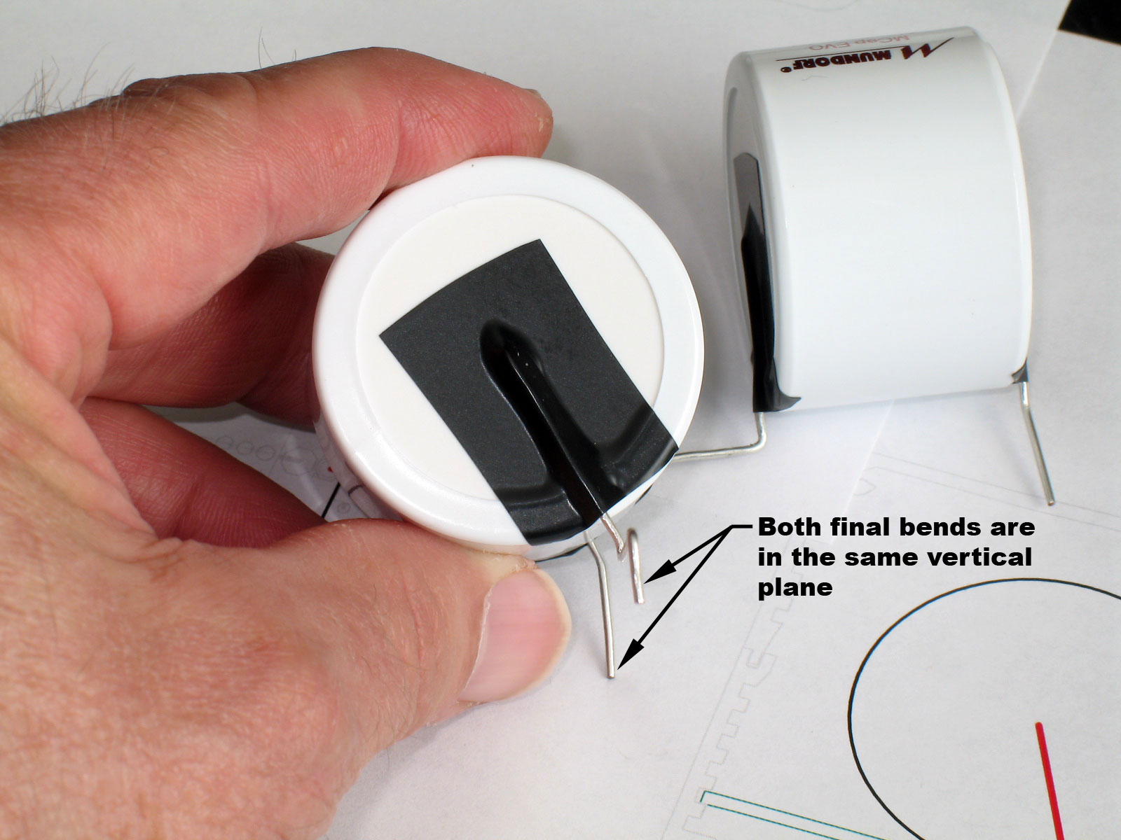
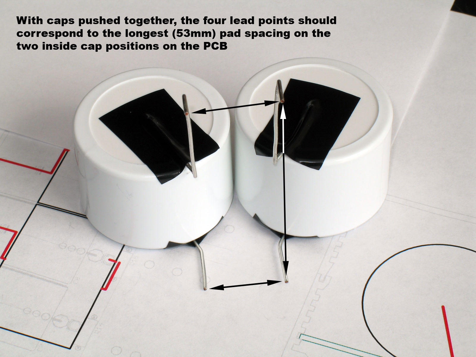
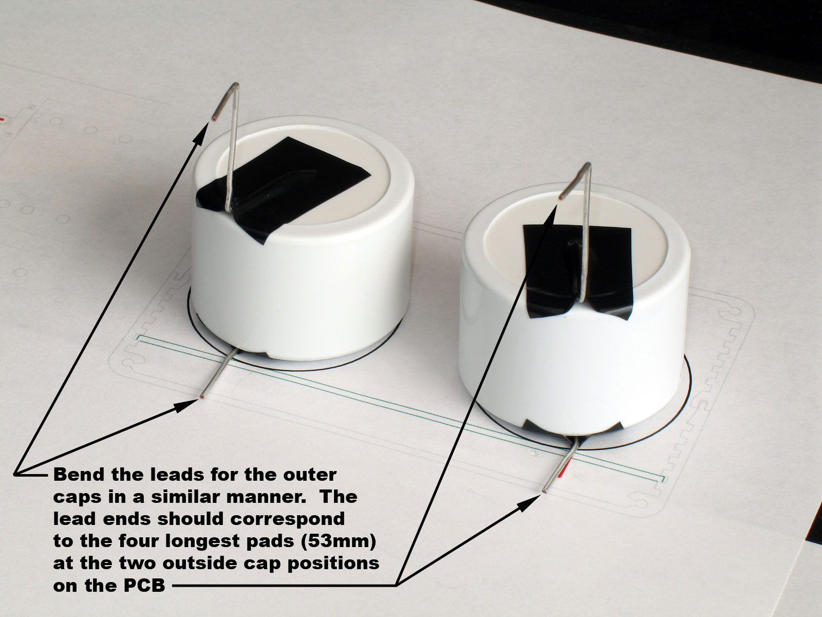
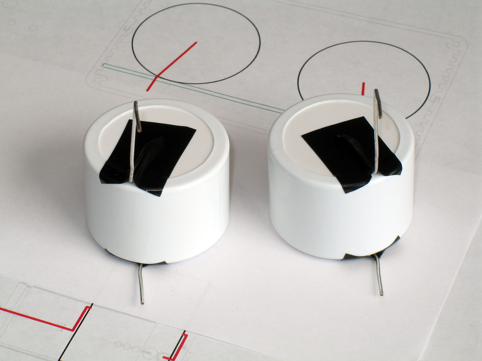
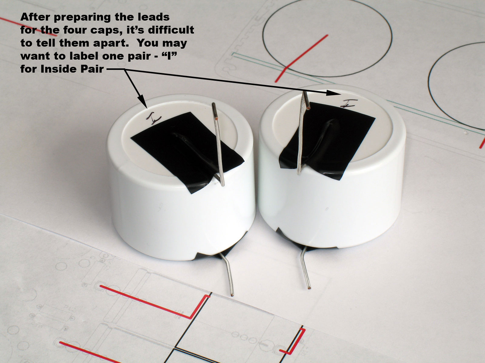
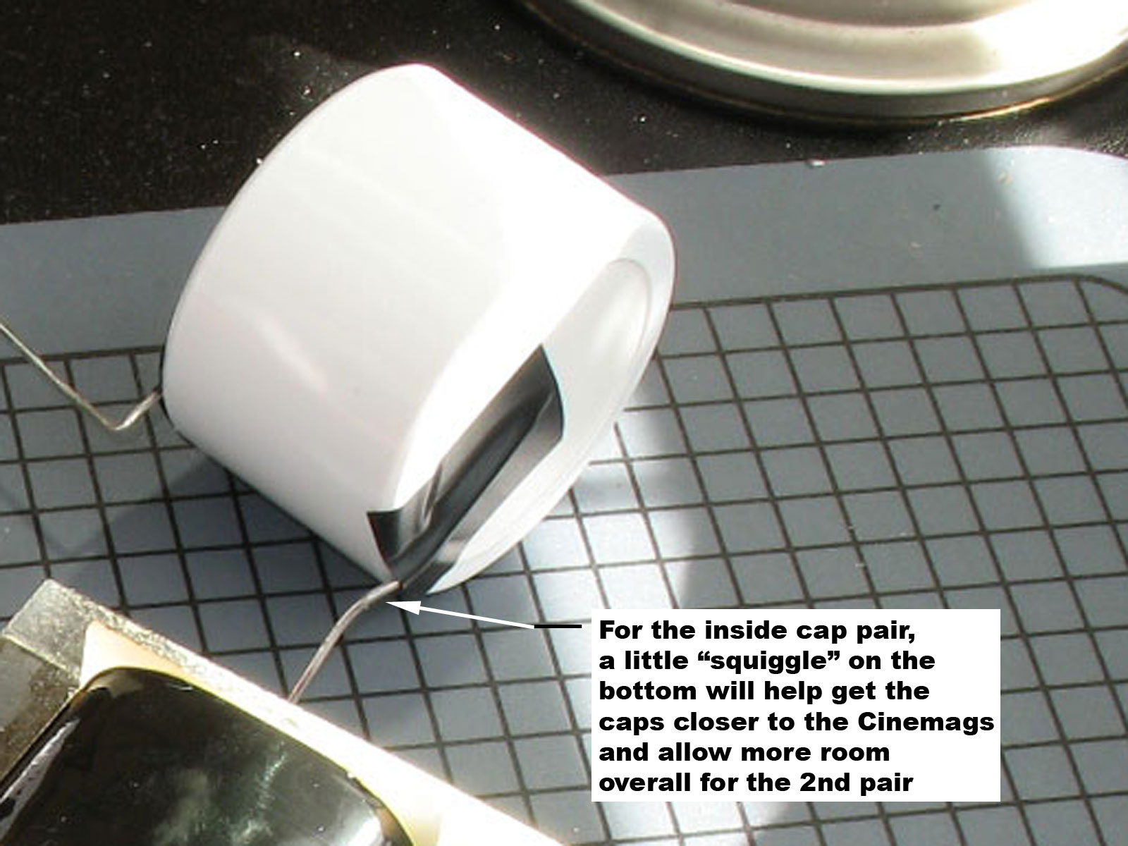
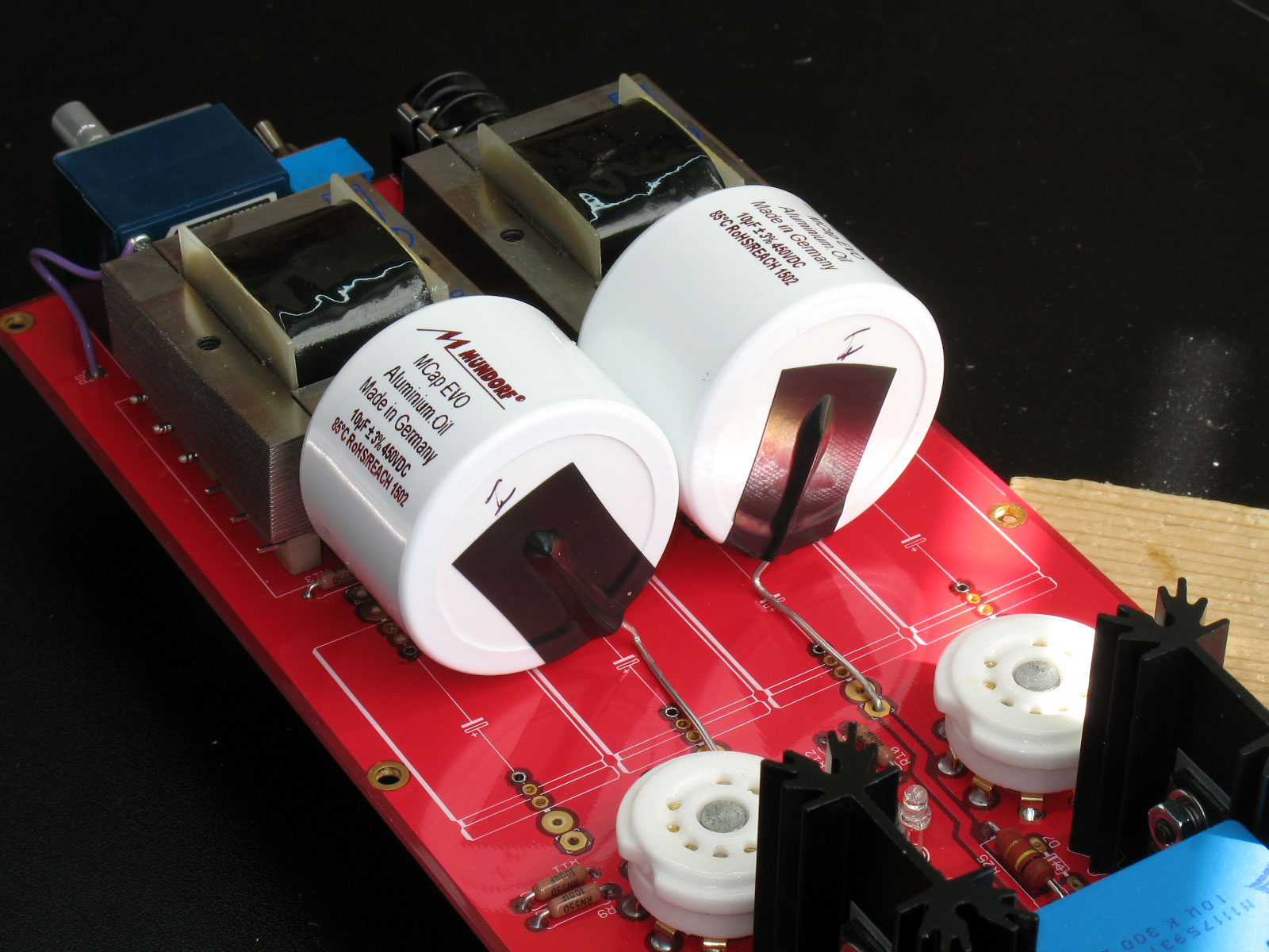
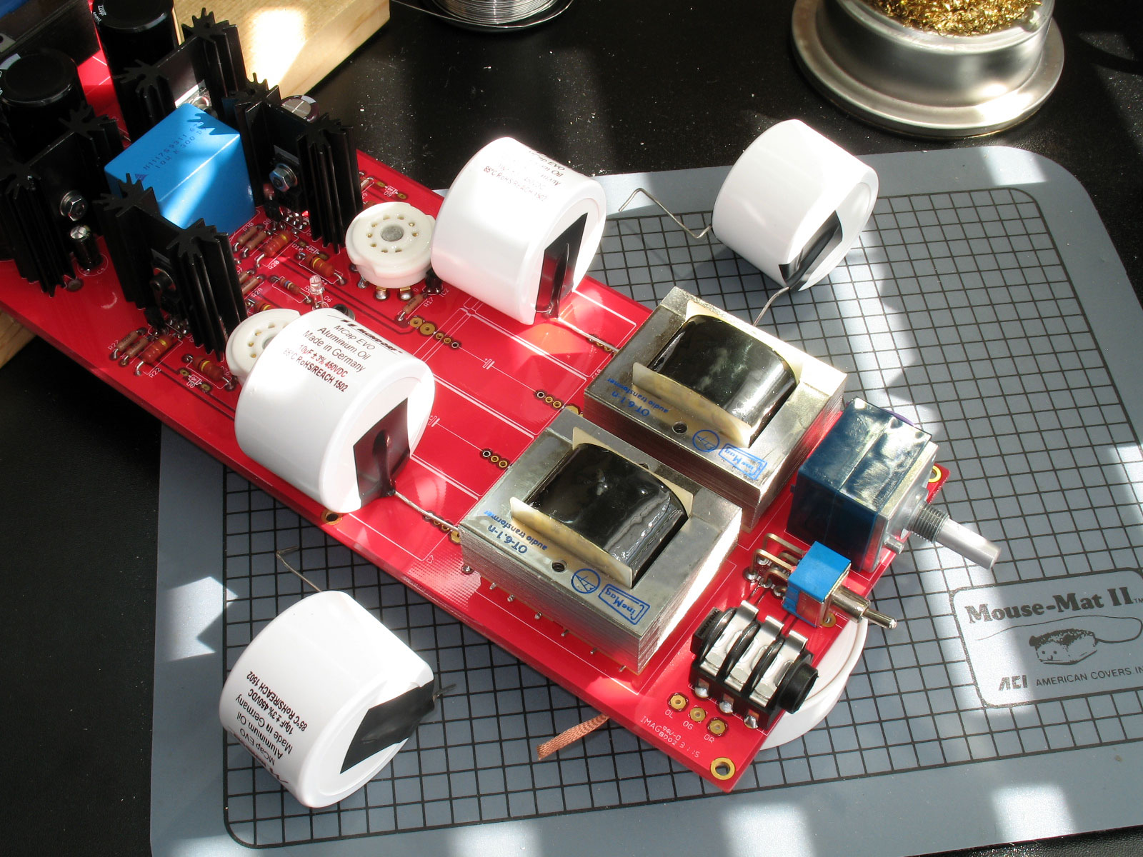
I picked the two inner caps to do first and to install them in the front next to the Cinemags. You may choose the reverse, but this is how I did it. On the printed template for the "Inside Caps," place the Mundorfs down so that their leads line up with the drawing. You can tell that the bend needs to start a slight distance removed from the outer edge of the capacitor diameter: Here we see both caps with their leads bent. The short leads have a single bend with the purpose of making the short lead perpendicular to the PCB. The long leads have the same bend in a mirror image. However, from the end of the bend, the long leads are bent horizontally out in the same plane as the lead on the other side. This horizontal lead will end up being parallel and flush to the top surface of the PCB. Here we can see the long leads bent into the horizontal much more clearly: The final step for the inner caps is to bend the long lead down so that it fits in the longest, outermost pad on the PCB. Note: depending on how much room your corner bends take, you may need to adjust this length of the horizontal lead. No amount of carefully templating or measuring these cap leads are going to replace some regular trial and error as you install them on the PCB. The drawings are guides, only. A drawn corner bend on the drawing is not going to match a bend you make with your fingers, or even with a pair of pliers. However, all of this effort should get you pretty close, making the job much simpler overall. Pardon my ugly fingers, but here is a good shot of one of the inner pair of caps, showing the leads and bends quite clearly in the same vertical plane. Why are we doing all of this? The idea is to fit these two inner caps on the PCB and their leads into the pads of the two inner capacitor positions. The outermost pads of each of the four cap positions on the PCB are 53mm apart. So, what you see below are the four lead tips corresponding to those four pads for the inner two positions of the parafeed caps: Next up are the outer caps. These are a bit more difficult, but the same techniques apply. Bend the leads on both sides to match the drawing. As before, the short lead only bends once and never in the horizontal. These will go into the PCB closest to the tube sockets. The long leads, on the other hand, must also be bent into the horizontal, then bent down for the 53mm distance between the pads as with the inner caps before. This ensures the maximum spacing and allows two pairs of these Mundorfs to be stacked in two rows in the Torpedo III, front to back: Here we see the two outer caps in their approximate spacing that will exist on the PCB. (The outer caps obviously do not touch each other.) The four points of those leads will correspond to the two outer parafeed capacitor positions on the PCB, each of which are 53mm apart, front to back. I thought of this afterward, but when you finish preparing all four caps, it becomes very easy to mix them up. I labeled my inside caps with an "I" on each one. Here we see a completed Torpedo III with the Cinemag output transformers. The four standard Epcos parafeed caps have been removed. (You can see them - among others - in the background on the table top.) My infamous little building board is pictured here, but a warning - you need to elevate the PCB on both ends so that you can trial fit the capacitors in the PCB without worrying about the leads touching the table top. You do not want to re-bend these leads because you've smashed them trying to get them in the pads with no clearance underneath. Similarly, if you trim the leads now, you'll have a very hard (impossible?) time getting them into position for soldering. Here we see the two inner caps placed into position, including the leads pushed into their pads on the PCB. Note how close the caps are to the Cinemags. There are actually resistors on the PCB that prevent the caps from moving all the way up against the Cinemags, but still - the tape is a good safety feature. Speaking of getting these close to the Cinemags, it helps to bend a slight "squiggle" into the leads at the very edge of the cap. This allows you to get them slightly closer (but not touching) to the Cinemags. Again, all of this is preparing to make sure the outermost caps will fit in behind these. Here we see the back side of the inner cap pair and their long leads run horizontally across the PCB to the longest distance pads right in front of the tube sockets. Looking closely, you can see that the leads didn't end up straight. You need to ensure that the two caps are pushed up against each other and that they meet in an imaginary center-line between the two Cinemags. Again, all of this is to save room for the other two caps. So bend, twist, re-bend the leads - whatever you need to do - to have the inner caps flush with each other, as close to the Cinemags without touching, and ensure that all of the leads on the opposite ends are run flush on the top surface of the PCB. Finally - DO NOT SOLDER THESE CAPS IN. YOU WILL NEVER BE ABLE TO INSTALL THE OUTER CAPS. As just noted, we now remove the inner caps - taking care not to affect the lead bends that worked. Then, place the outermost caps into position on the PCB. Make certain they are not bending the regulators in front of the tube sockets. (Remove the regulators IC1 and IC2 and install on the bottom of the PCB, if needed.) As before, ensure that the long leads are flush with the PCB. The other caps will not sit on top of these leads, but they will overhang quite a bit. So, it's still important to ensure that they are flush with the PCB. Finally, if you are happy with the fit of the outer caps, then re-install the inner caps. (You cannot do this in reverse - inner caps first, then the outer caps - it won't work.) Check all of the clearances. Make sure the caps are not touching the Cinemags and make sure the outer caps are not touching the tube sockets or that they hang over the outside of the PCB. However, you can make this work - do it. The object is to get to where you can flip the PCB over and solder the eight leads on the bottom of the PCB. Here's another use for my infamous little pine building board. Flip the board over on top of the caps and while holding the case bottom and the board tight down on the top of the Mundorf caps, flip the entire thing over so that the amp and Mundorfs are pushing down on the building board. Use a pair of pliers, if you have to, ensure that the leads are pulled all the way through and flush on the top surface of the PCB on the other side. Solder into place on the bottom of the PCB. Here's a pic of the final result. In this example, the caps are very slightly twisted outwards toward the back of the amp. No matter - they are in, they fit, they're secure, and they work! Your mileage may vary ... A view from the backside: Enjoy your Mundorfs! You deserve it! | ||||


file last changed:Friday, August 26, 2016 2:33:52 PM
Please contact the TORPEDO III webmaster for questions about these web pages.
