Buy Kits & Parts:
www.beezar.com
www.beezar.com

The ECP Audio
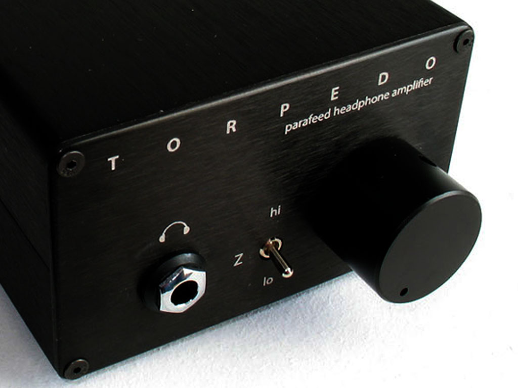
T
O R P E D O
| III |
differential hybrid parafeed headphone amplifier
| |
Technical Highlights
The TORPEDO III is the latest DIY design from Dsavitsk of ECP Audio. Based on the successful Torpedo planform, the Torpedo III is also of parafeed design, but differs in the unique differential amplification stage prior to the output transformers. The dual-triode tubes are configured in a long-tailed pair circuit, whose differential output is further amplified by a high-voltage differential solid-state circuit before input into the output transformers. The result is a totally unique headphone amplifier. The differential circuitry inherently rejects all commond-mode distortion. The output results in a remarkably, fatigue-free listening experience. When combined with the optional Cinemag output transformers, highs are extended and details are increased to a world-class level of performance. Details of the circuit design are described below. In addition, one of the finest papers written on the subject of parafeed circuits can be found here: The Basics of Parafeed (by Dsavitsk, of course). All tube parafeed amplifiers incorporate a vacuum tube gain stage that is AC-coupled to an output transformer. The TORPEDO IIII is no different, but the entire circuit is differential between the input/volume pot and the output transformers.
| Dsavitsk explains the TORPEDO III circuit (refer to the Schematic page from the menu):
The power supply begins with the bridge rectifiers after the power transformer, one rectifier for the tube heater supply, and one for the amplifier circuit itself. Diodes D3, D4, and D5 bias the gate of MOSFET Q1 to ~225VDC. This sets the regulated voltage for the amplifier circuit (B+).
The tubes are configured as a Long Tailed Pair, which is a differential circuit that acts as both a gain stage and a phase splitter. R17 (R18 for the left channel) sets the current through the Constant Current Source (CCS) in the tail of the tube to about 2mA. The 2mA of current is split between the two sides of the tube with ~1mA per side. Each plate in the tube is loaded with a 100K resistor (R23, R24, R25, and R26). This means that the tube plates operate at approximately 125V [225V - (100K * 0.001A) = 125V]. Each plate is directly coupled to the base of an NPN Darlingtion transistor pair. Each emitter of the Darlington pair is loaded with a 22K biasing resistor (R19, R20, R21, and R22). Since the transistor bias voltage is at 125V, the 22K resistor causes ~6mA to be drawn per transistor (125V/22K). This results in 12mA per channel of standing current. A step-down output transformer is AC-coupled and bridges the two emitters. The transformer's winding ratio is approximately 6:1 into the high-impedance section and 18:1 into the low impedance section. This means that there is effectively 70mA of current available for high-impedance loads (also ~20V for ~1.4W) and 200mA for low impedance loads (also ~6.5V for ~1.3W). |
|
The circuit is designed to work well with most of the 12A*7 family of tubes, but is optimized for the 12AY7. Different tubes will provide different levels of gain, but some types may not perform as well as others, with high-frequency performance possibly suffering in some instances. The 12AY7 provides optimal performance and approximately 6X (15dB) gain into 300 ohm loads and 2X (6dB) into 32 ohm loads. Other tubes are shown below:
| Tube Type | gain - 32 ohms | gain - 300 ohms | ||
| 12AT7 | 2.3X | 7dB | 7X | 17dB |
| 12AU7 | 0.5X | -6dB | 1.5X | 2dB |
| 12AV7 | 1.3X | 2dB | 4X | 12dB |
| 12AY7 | 2X | 6dB | 6X | 15dB |
Notes on some specific tubes:
12AU7 - probably has too little gain to be very useful, but if you have a particularly hot source and/or tend to listen quietly, it might be worth playing with.12AX7 - has a higher mu (gain) than the other tubes listed, but it also has a higher plate impedance. This will result in lower gain and some high frequency loss. It might still be worth playing with, but it is probably not the ideal tube here.
12AT7 - has similar looking gain to the 12AY7. However, the circuit runs it at lower voltage and current than are idea which will result in slightly higher distortion. Subjectively, we found it to sound more tubey which some people may like.
12AZ7 - looks like another decent option, but I have not tried it.
6DJ8, 6922, 6H6, 6H31, 6N23, 6N1P, etc. are not compatible with the circuit. At the very least, if you try them you'll probably damage the tube, but there is a good chance you'll damage the amp, too. If you are in doubt about a particular tube, please ask before you try it.
Features of the TORPEDO III:
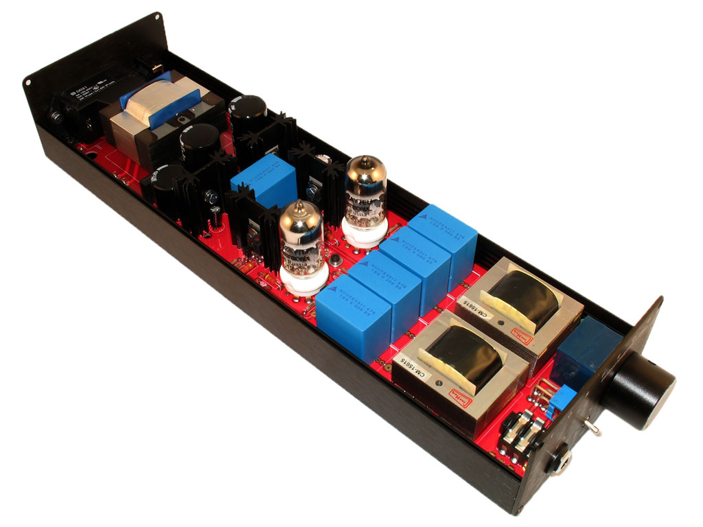
- The tube/hybrid differential design with output transformers,
- Single, PCB-based design. No high-voltage power wiring required!
- Extra long PCB to prevent magnetic coupling between the Power Transformer and output transformers.
- Switchable between high-impedance headphone output and low impedance.
- Based on the ubiquitous 12A*7 tube family (optimized for 12AY7).
Like the TORPEDO! before it, the TORPEDO III offers the most integrated board design yet available. All connectors are PCB-mounted. Except for one small ground wire to the Alps volume pot and a safety ground, there is no other wiring required, whatsoever.
file last changed:Saturday, June 25, 2016 10:26:40 PM
Please contact the TORPEDO III webmaster for questions about these web pages.
