Buy Kits & Parts:
www.beezar.com
DIYForums.org
The ECP Audio       T        O        R        P        E        D        O      
III 
differential hybrid parafeed headphone amplifier
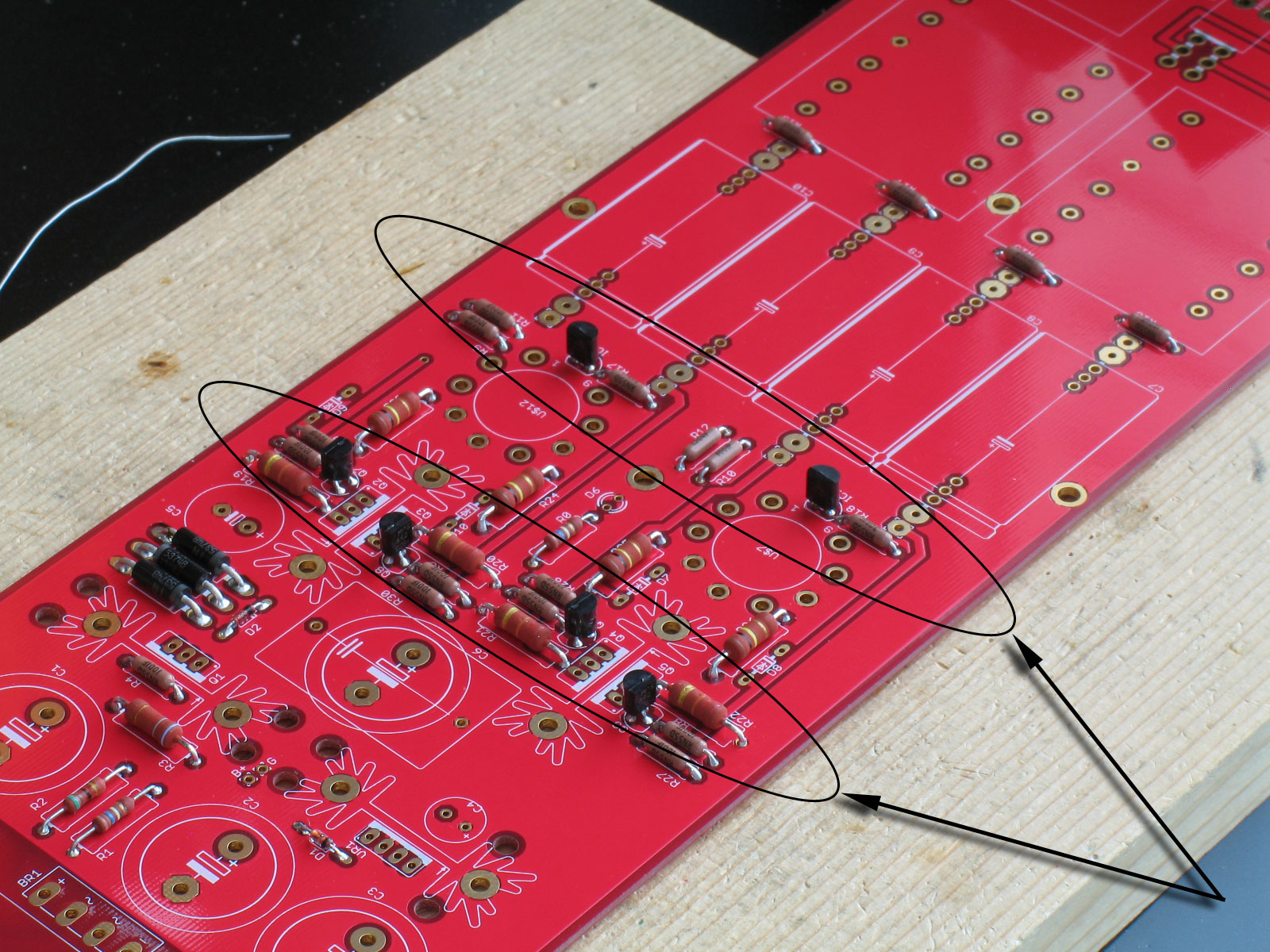
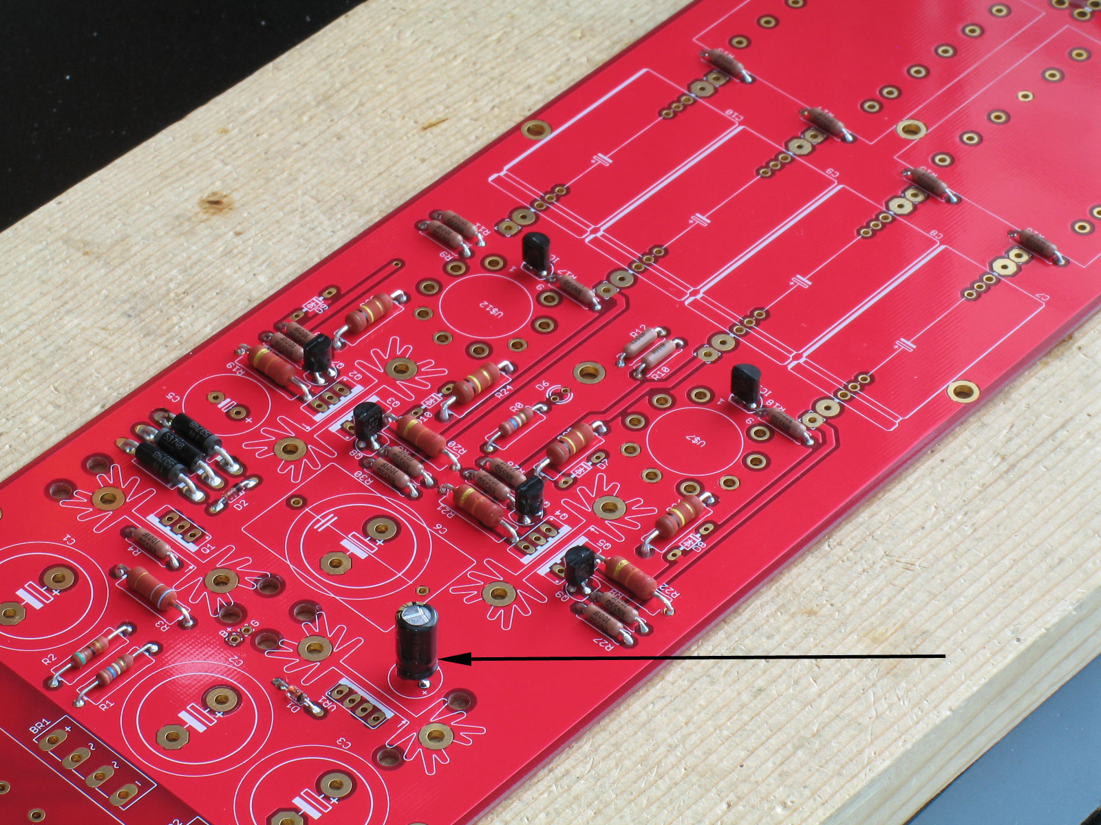
Construction - PCB part 2

Next are the TO-92 parts:

Note the two by the tube sockets. These are actually integrated circuit regulators. DO NOT SOLDER THEM COMPLETELY FLUSH TO THE PCB. We'll show why later when we solder in the tube sockets. Again, if you are using my pine board method, you should be able to insert all of the TO-92 devices, flip the PCB over and have the TO-92 devices support the PCB upside down while you solder the joints.

The smallest electrolytic capacitor goes in next. The ones supplied with the kit and on the BOM have the type of leads with the "kink" or "knee-bend" in them. So, don't worry about trying to get the cap flush to the PCB.  Just make certain the cap is securely soldered and is stable.

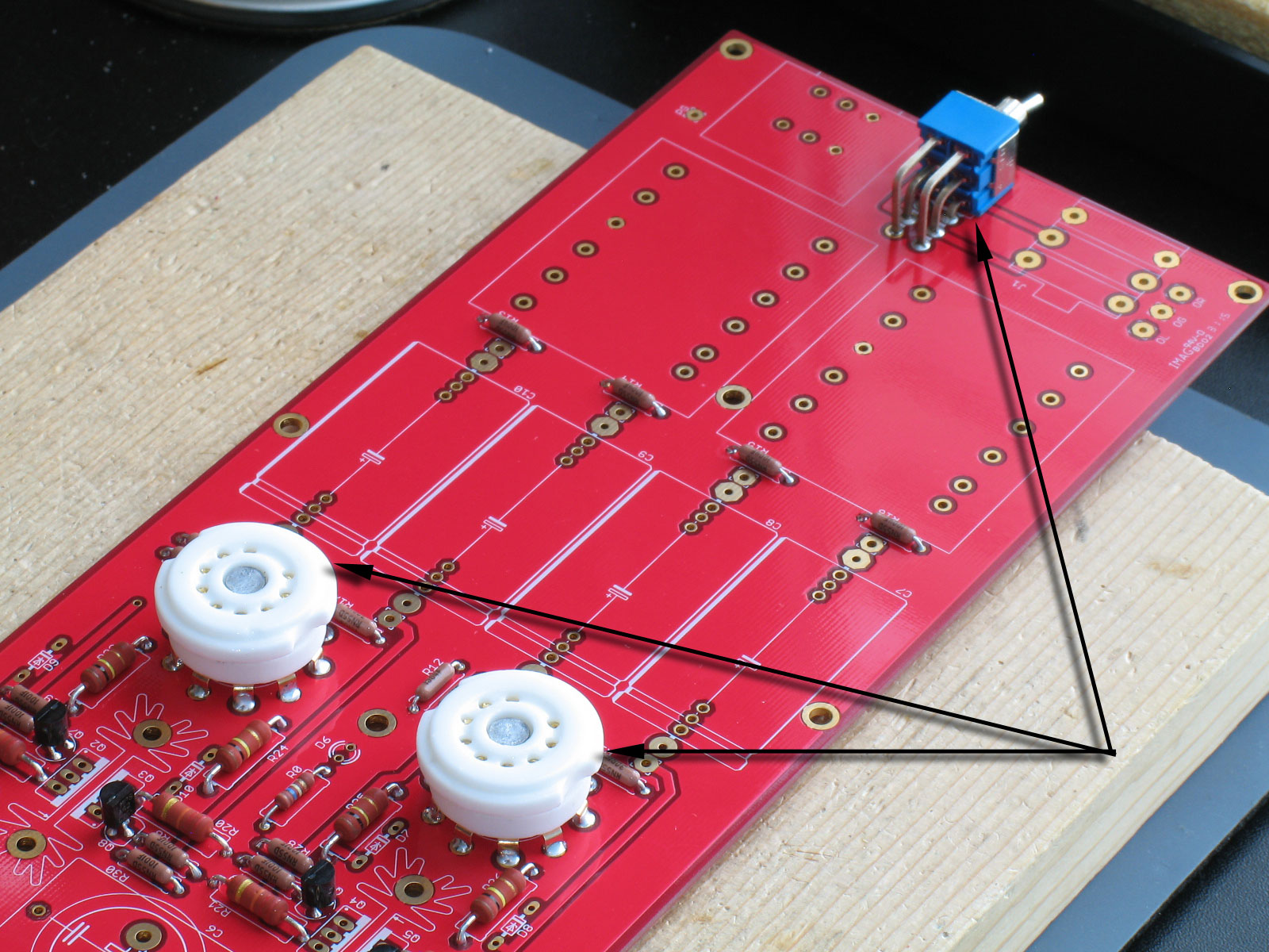
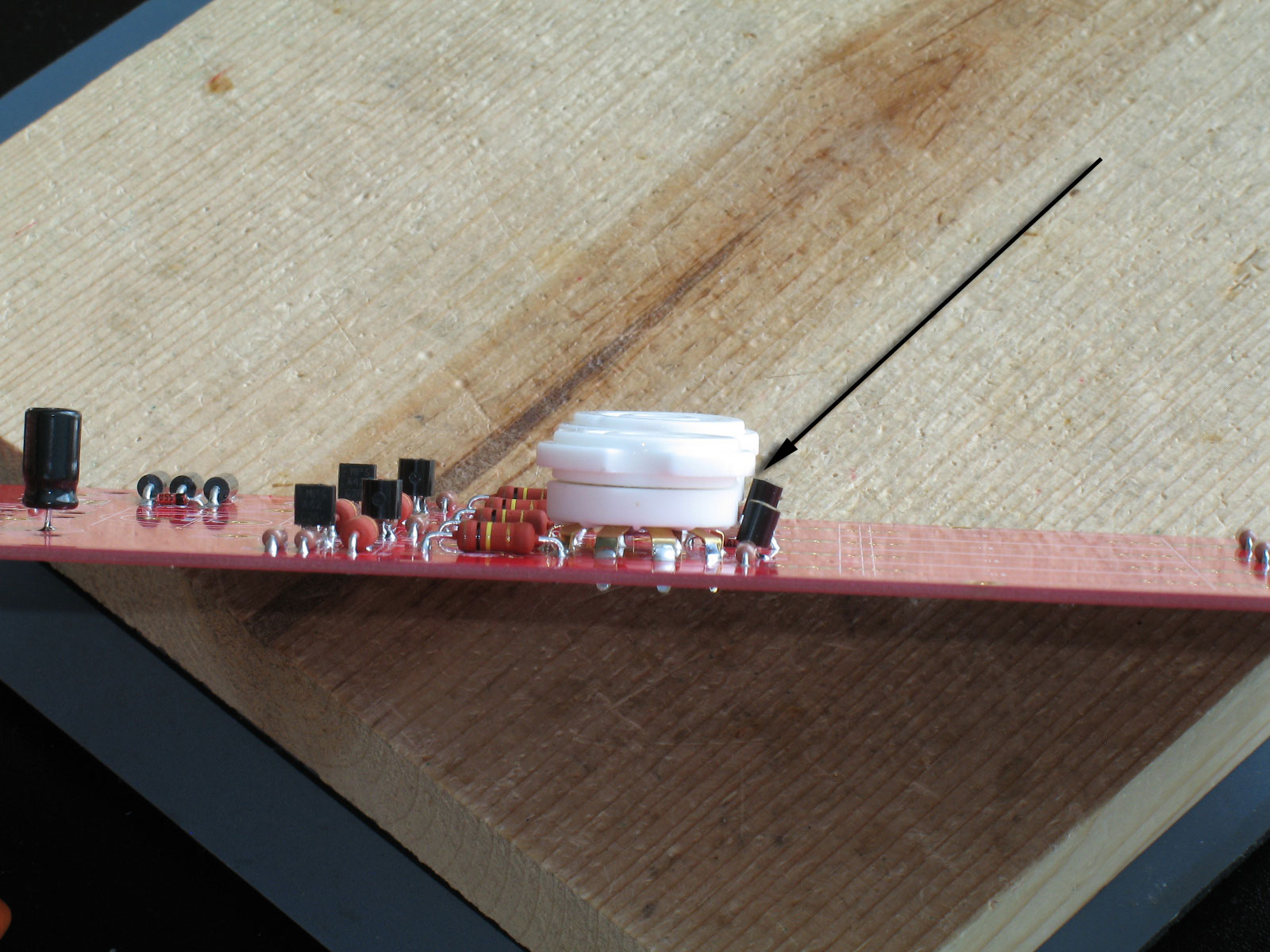
Next up in height are the tube sockets and the Z-switch. All three are about the same height:

As in mentioned in many of my build threads and on the website, remember that the tube sockets are just as much a mechanical/structural connection as they are electrical connections. So, ensure that the joints on the pins are good and sufficiently soldered. While soldering from the bottom of the PCB, the solder should be sufficient to wick all the way to the other side and some length up the pin legs. That said, please refer to the very next pic and description below before soldering the tube sockets into place.

 NOTE: Notice that those are 9-pin sockets!

Similarly, the joints on the Z-switch must be sufficient and secure. However - in the case of the Z-switch - the body and much of the inside is plastic, so wait between soldering each joint and allow it cool. Otherwise, you could end up with a plastic puddle on the PCB instead of a nicely installed switch.

 As mentioned, here is the reason we do not want to solder the TO-92 regulators (IC1 and IC2) in front of the tube sockets flush to the PCB:

The real estate on the Torpedo III PCB is very limited. In this case,IC1 & IC2 were moved forward as far as possible with endangering the traces beneath by having them too close to the output transformer traces.Even so, they must be bent forward slightly to make room for the tube sockets. You should be able to bend them far enough forward that no part is touching the tube sockets. Don't solder the sockets in until you are assured that the regulators are not touching.


file last changed:Saturday, October 31, 2015 6:53:24 AM
Please contact the TORPEDO III webmaster for questions about these web pages.