Buy Kits & Parts:
www.beezar.com
www.beezar.com

The ECP Audio
T
O R P E D O
| III |
differential hybrid parafeed headphone amplifier
| |
Construction - Final Assembly
|
Final Assembly! Slide the PCB into the rear of the case (remember the back plate is still attached to the back of the PCB) using the 2nd slot from the bottom. You should have the two standoffs attached to the PCB at this point. The standoffs (4-40 x 5/16" tall) should include a single #4 flat washer between the standoff and the bottom of the PCB to get the spacing exactly correct. Attach on the top of the PCB with a 4-40 x 3/8" long socket head cap screw, a lock washer, and a flat washer against the top surface of the PCB. The lock washer on the top side (a bit counter-intuitive from conventional practice) ensures that the screw stays locked when you attempt to remove the screws from the bottom of the case that go into the other side of the standoff. Believe me, I've had one of the top screws come undone while inside the case. Be prepared to dis-assemble the entire backplate to get it out. So, use the lock washer on top! As noted above, there are two spots available for the standoffs. The Torpedo I uses three, but we were being especially cautious on that design when using a PCB as long as these are. Regardless, one of the standoffs in the Torpedo III goes right between the tubes, which is where the PCB experiences the most stress (from plugging and un-plugging the tubes). This has worked out fine for the Torpedo III and with four prototypes in the books, there are no problems with support. Here's a look at the bottom of the case -  Use a 4-40 x 1/4" long socket head cap screw with a single flat washer to screw into the standoffs from the outside. You probably won't be able to get the screws screwed in all the way flush to the bottom of the case - there simply isn't enough room for threads in the standoffs. However, the washer + standoff is completely flush with the PCB and the inside of the case so there is no up and down movement. Overall, the PCB is completely locked from any up and down or sideways movement. If it worries you that the bottom screws are not completely flush, use another flat washer under the screws on the bottom of the case. I think that leaves precious little threads in the standoffs to really grip the screws, but I've done it both ways in the past. There will be plenty of washers included in the kit. Also note that with a case this long, it just seems a bit better to use bumpers in the middle, besides on both ends. You can see the third standoff position is simply an open hole with the Torpedo III. It is, after all, the very same case used for the Torpedo I. Here's a view of the safety ground screw underneath the PCB: 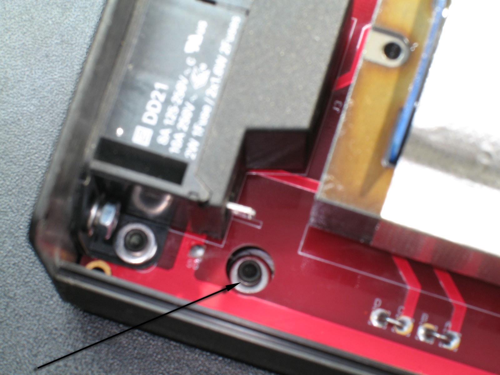 NOTE: before assembling the PCB, use a knife or file to scrape away the anodizing on the INSIDE of the case around the safety ground hole! Aluminum anodizing has insulating qualities and you will not get a good safety ground connection if you don't do this! When assembling, I push the PCB in until I reach the safety ground opening in the PCB that you see here. Then I check to make sure the safety ground wire and lug assembly is clearing the case and that the lug is lined up with the hole. Then I push the PCB in the remaining length. There is usually enough friction on the end of an socket-head ball-driver to hold the cap screw and two flat washers (for spacing) sideways. So, with the Torpedo III resting sideways on the side of the case, I insert the cap screw/washer collection through the PCB hole and through the hole in the lug underneath. Before you do all of this, use the socket-head ball-driver to line the lug up with the mounting hole on the bottom of the case, if you can. Then while the wire/lug is suspended in position, use the ball-driver to push the screw/washer collection through the PCB hole, through the lug, and through the hole in the bottom of the case. If you mess up, just pull the PCB back out a bit and shake the screw and washers out. Push the PCB back into the case, line up the lug with the holes, and try again. Once you get everything pushed through to the bottom of the case, then apply another flat washer against the case, a lock washer and a nut. Tighten everything up and continue assembling the rest of the case. Here's a closeup of the safety ground nut and washers on the bottom of the case: 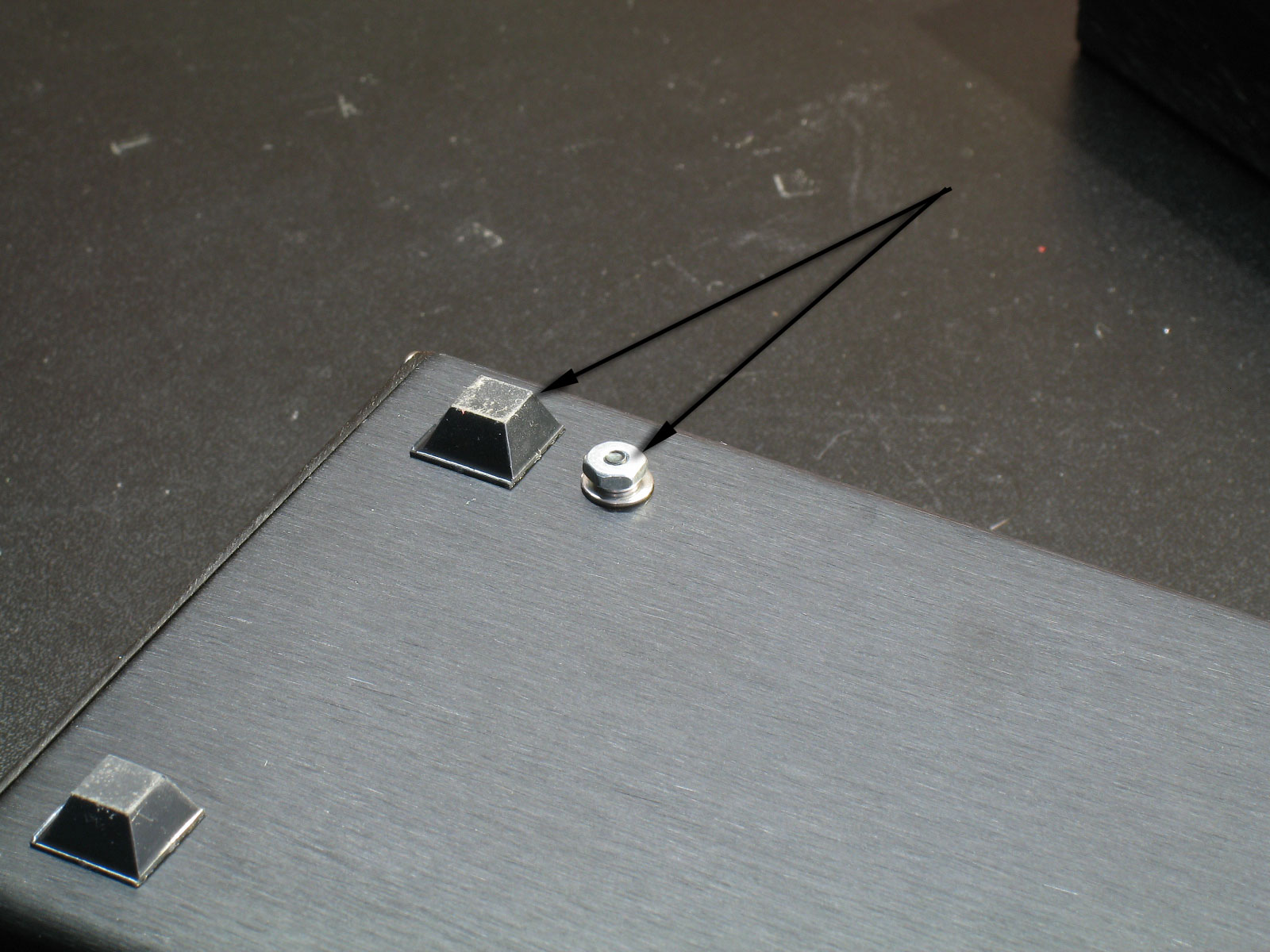 Note the proximity of the height of the washers/nut assembly to the height of the bumper. This is close. It's why I said use two washers under the socket head of the cap screw on the inside. A 1/4" socket head screw is simply too short to manage poking through those holes, but a 3/8" screw is going to stick out from the bottom of the case further than the bumpers. This would not be good for your furniture! So, be sure to use two washers under the screw head before poking the screw through the lug and holes from the topside. The next step is to screw the 1/4" socket-head cap screws with washers into the two standoffs! |
Assembling the rest of the case is pretty easy. Besides a 4-40-sized socket head ball-driver (or allen wrench), you need the following shown below -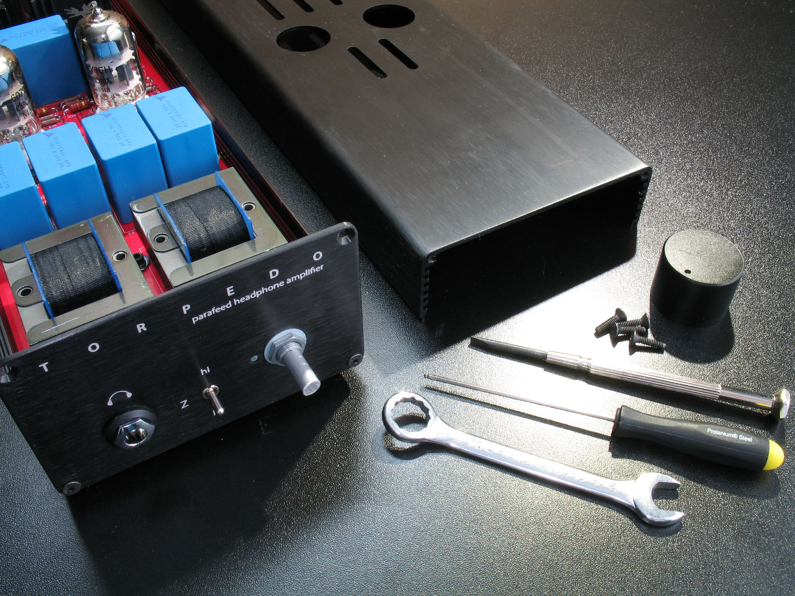 I've already cheated and attached the front plate and back plate on the bottom. However, you see the tools in this pic that you can use. No, you don't really need them, but they will help you from scratching up the case. Both the Alps volume pot and the Neutrik headphone jack use 7/16" diameter nuts. A small closed-end 7/16" wrench is a great tool and won't scratch things up. Remember that you're dealing with plastic, here, so don't go torquing the heck out of those nuts! They only need to be snug! The other great tool, especially for the counter-sunk 4-40 socket head screws is the Bondhus 1/16" ball driver.This tool is so convenient for removing the screws of the top case lid that I provide one with every Torpedo kit sold! NOTE: You need to remove the case lid to change out the tubes. That means this might be done quite a bit. The Bondhus driver is really handy for that! Finally, a precision screwdriver is used for the volume knob. This is not really necessary, though - it's just that you need to have a screwdrive whose blade is thin enough to fit through the hole. I purchase the 30mm aluminum knobs from PartsPipe/hongkongsuperseller on ebay. They seem to have the best, large knobs that don't break a wallet, but consistency is sometimes pretty bad. I've gotten them with flat-head set screws, allen set screws, and once even got a bunch with two set screws. Use the tool you find most convenient. Here's a pic using the wrench on the volume pot nut. You should attach the front plate to the pot and headphone jack, first. Get the nuts snug, but not overly tight, then screw in the front plate screws to the case extrusion. Dsavitsk mentioned that he does the front plate in a similar manner as the back plate. In other words, he attaches the headphone jack and the volume pot to the front plate, then solders them into the PCB. That's one way to make certain you get the headphone jack and pot straight, so you might try that if you're interested. 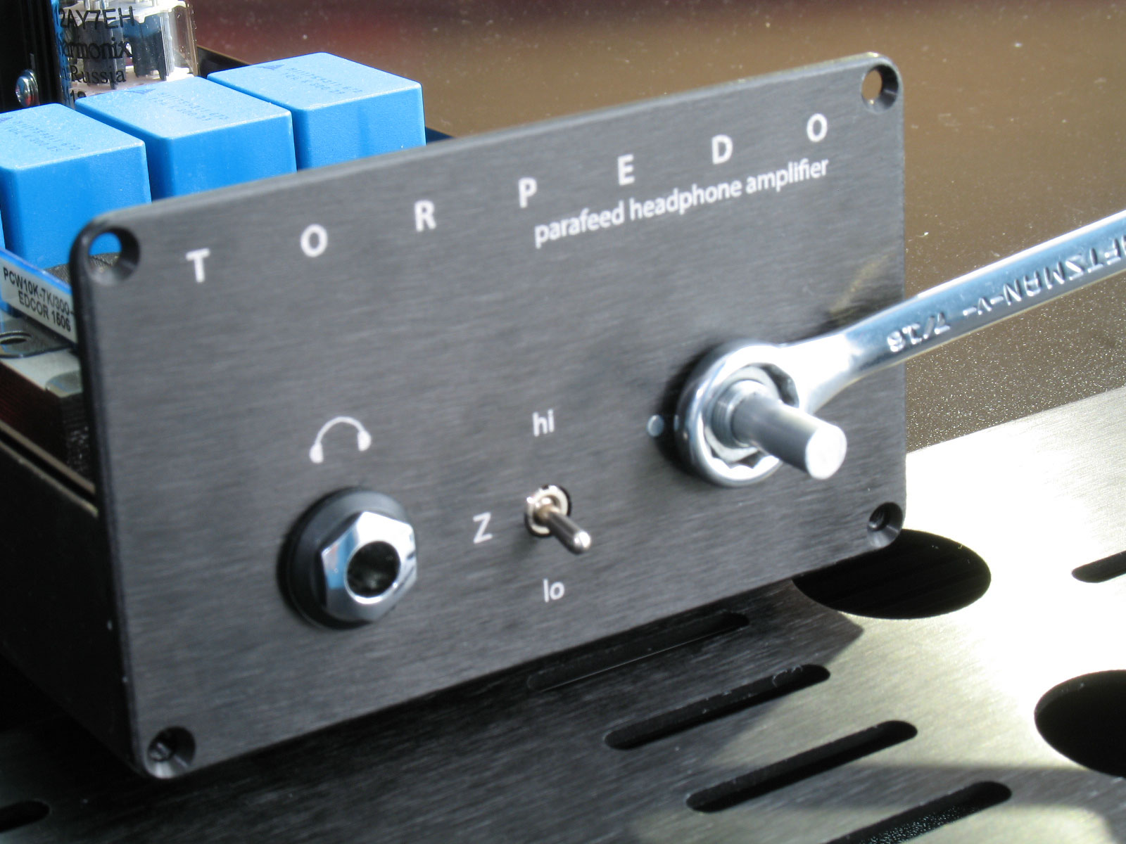 The headphone jack comes with three spacers, a tapered spacer and the ferrule nut. I use a single spacer on the inside, then one spacer, the tapered spacer, and the ferrule nut. I just think that looks best, but you might like another spacer in front or only the tapered spacer - it's up to you. There's no pic for this (and I cheated again by already doing it), but you need to cut about 1/4" off of the ALPS shaft to get the knob flush. I do this with a Dremel cut-off wheel, after I package up the case in a small plastic garbage bag. I poke a hole in the bottom so the pot shaft can poke through, then I tape all around the shaft and the garbage bag at the hole. This makes certain that no aluminum dust gets into your Torpedo and makes a fuss with that high voltage! You may have a different method. Use what works, but the idea is to protect the insides from any metal dust. The Dremel cut-off wheel can be a hassle. What happens is the top and bottom surface of the wheels will get loaded up with aluminum, forming a sort of ring toward the outside. This will make the wheel catch in the cutting throat of the pot shaft and then snap! With care, you can prevent this from happening, but I haven't found any real bad effects once the cutting wheel snaps. (Wear safety glasses, though!) Some people have suggested using a hack saw before, but think that just puts a lot more stress on the pot, its internals, and the solder joints. Whichever method you use, though, go slowly and be sure to protect the rest of the amp from the metal dust that results. When you're ready to mount the volume knob, use a credit card or similar to wedge in under the back of the volume knob. This will give you the closest spacing without having the knob bind against the front plate. Here is the amp with both end plates screwed in at the bottom:  I haven't mentioned this much, because it has little to do with actually building the amp, but note the tubes. The Torpedo III can use just about every 12A*7 tube made - 12AU7, 12AT7, 12AY7, 12AX7, etc., and all their variants. I ran the second prototype with 5963's, in fact, and it sounded GREAT. However, Dsavitsk's design is really optimized on the 12AY7 for the best all-around gain. So, two modern, new manufacture Electro Harmonix 12AY7's will be supplied in all of the kits. The rest of the tube rolling will be left up to you. Here's a pic of the back plate, since we've seen so much of the front plate. Yes, I've already attached the lid in this pic. Regardless, note the socket head screws, black washers, and the IEC inlet with the rectangular section poking out properly. Oh! I forgot to mention to screw a 4-40 socket head cap screw + black flat washer into the RCA jack assembly. This is the screw/washer you see below between the IEC inlet and the RCA jacks themselves. The plastic is so soft for the RCA jack assembly, that even the 4-40 screw self-threads itself when you screw it in. Again, this is plastic you're dealing with, so get the screw/washer snug and flush, but don't go torquing crazy! 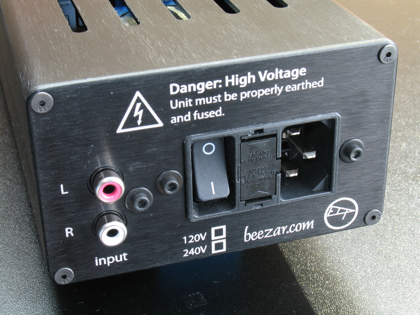 Finally, a couple of shots of the completely assembled amplifier - Front:  and Back - 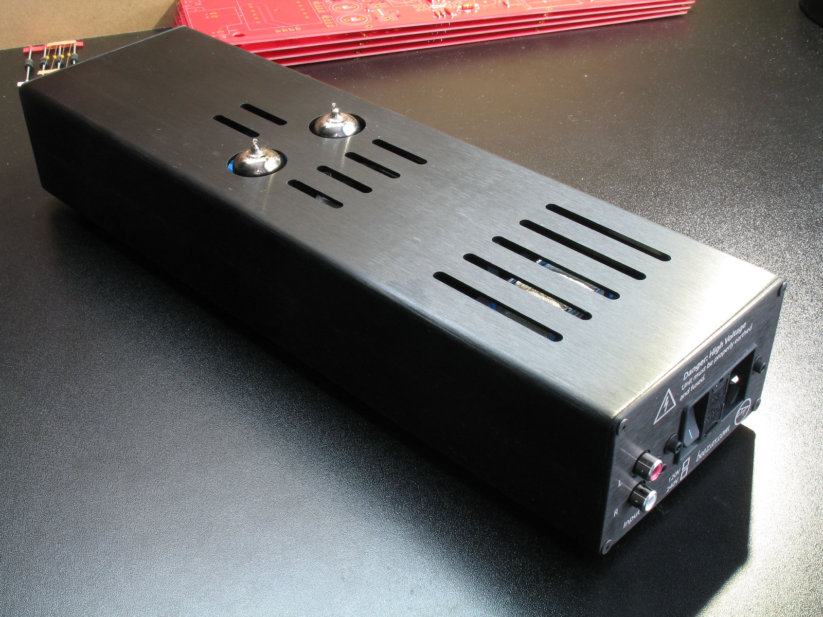 DONE! |
file last changed:Saturday, October 31, 2015 8:48:56 AM
Please contact the TORPEDO III webmaster for questions about these web pages.
