www.beezar.com

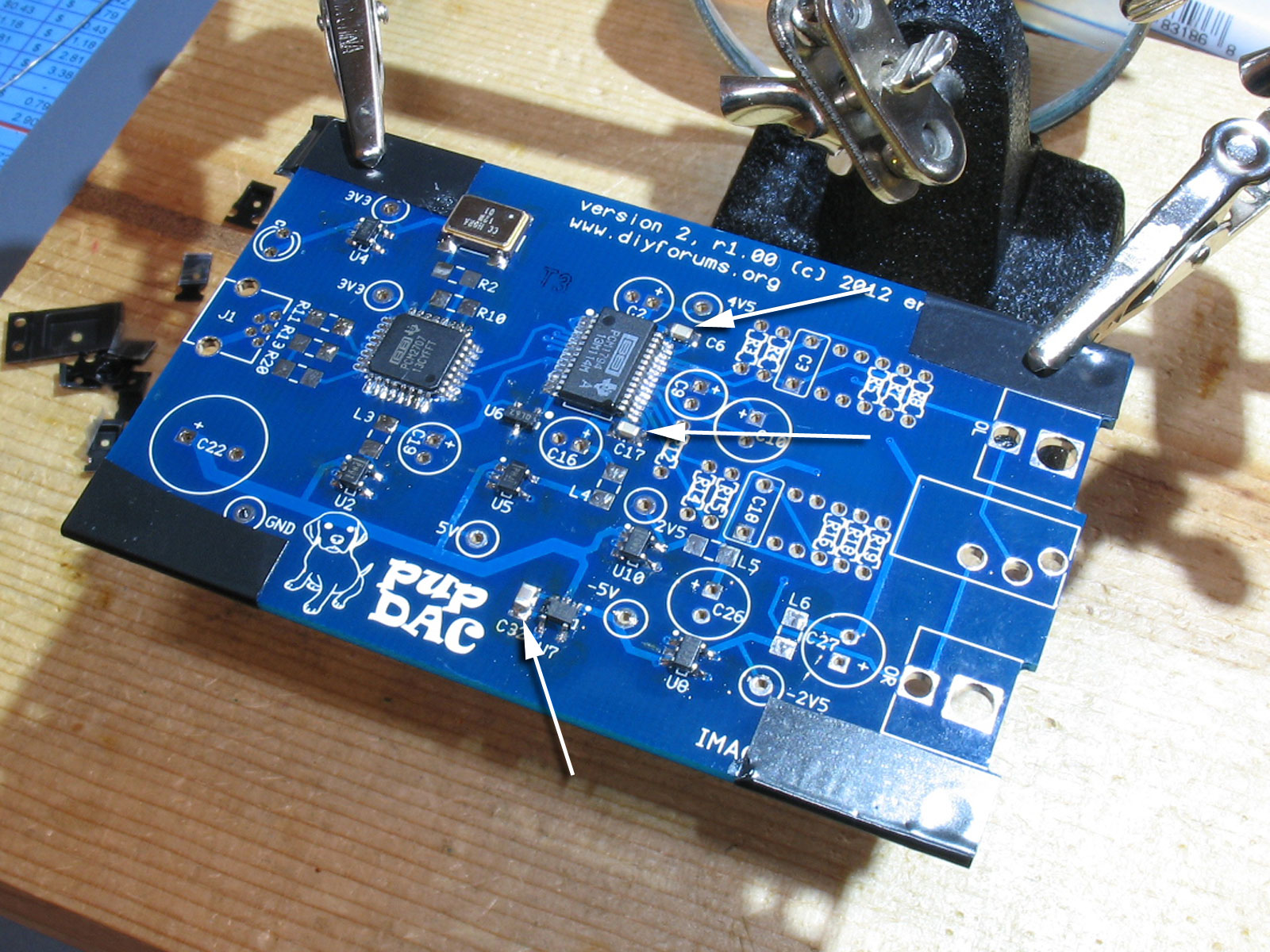
At this point, you have a lot of tiny SMD parts left to solder. As mentioned previously, the Beezar/Mouser kit has been packaged from Mouser with their part numbers on the bags. So, you need the BOM to reference the part numbers with the pupDAC part #'s used on the PCB: Next up are the rest of the "U" chips. All the remaining "U" chips on the top side of the PCB are TPS regulator chips, except for two. One is a supervisory controller, U6, and the other one is the charge pump, U7. Except for the supervisory controller which is SOT-23-3, all the other "U" parts are SOT-23-5. The five-pin chips have 3 pins on one side and 2 pins on the other. I've found it's easiest to anchor and place the chip using the middle pin on the 3-pin side. Note that the single remaining "U"" chip is the U9 opamp that gets soldered on the back side.
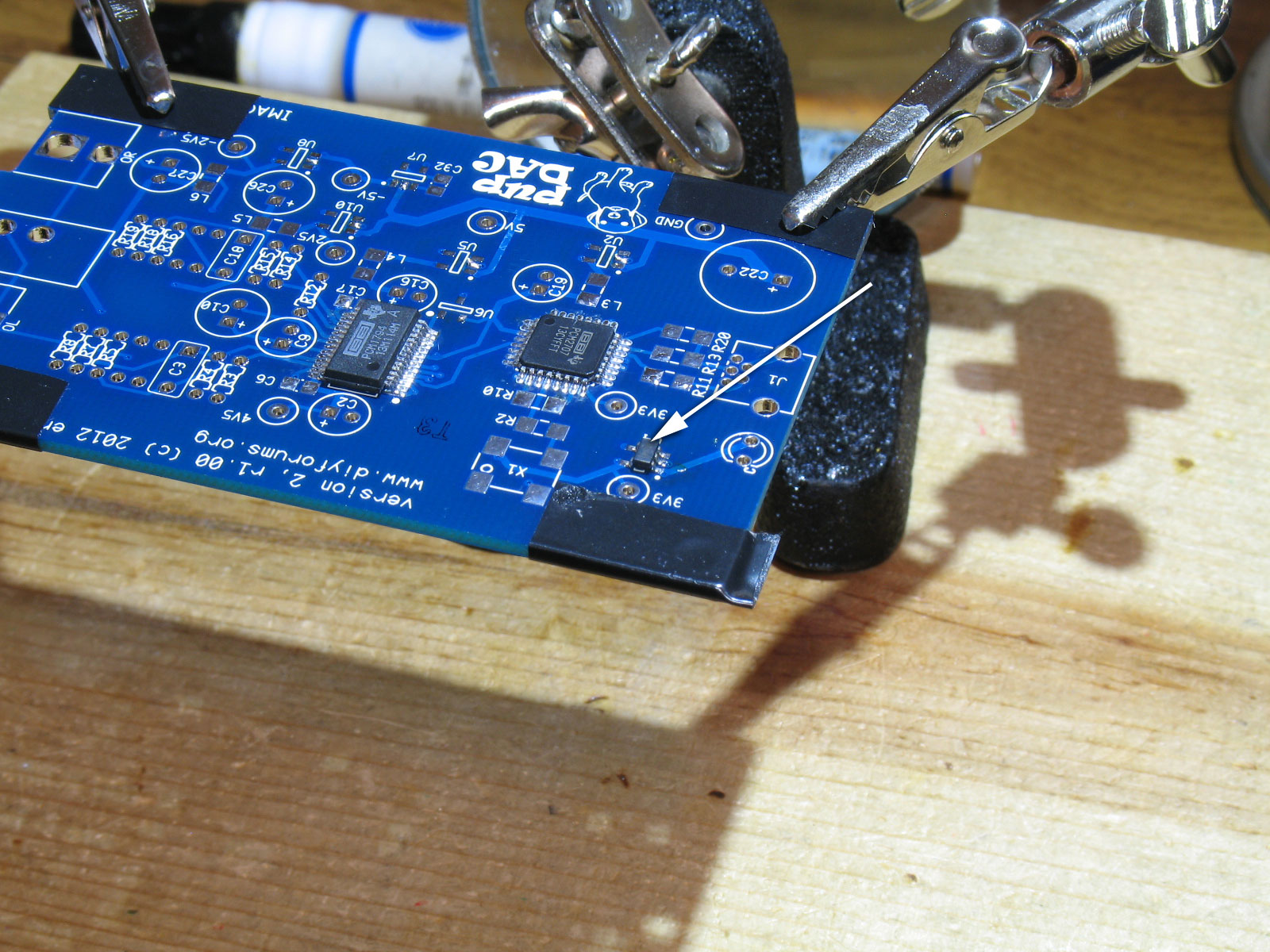
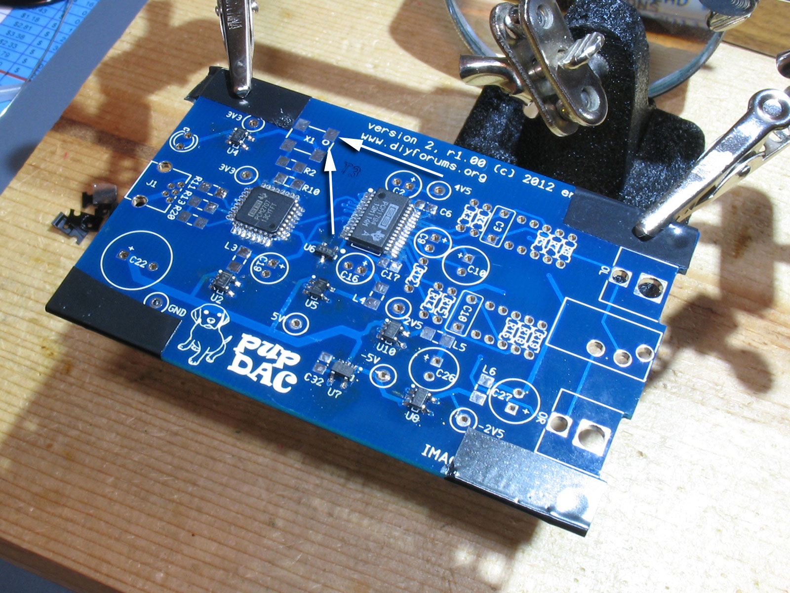
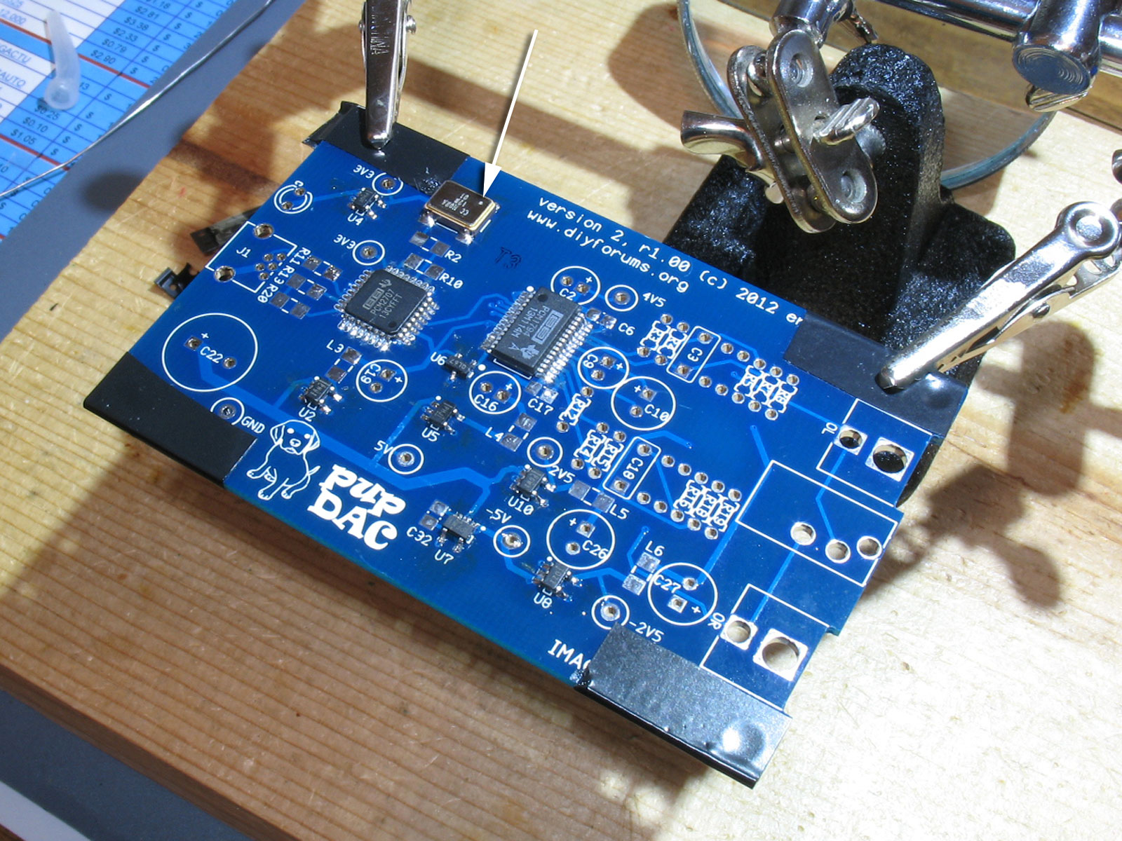
Using the middle pin on the 3-pin rows like this gives you maximum accessibility to solder all of the other pins. Since almost all of the 3-pin rows are on the left side, I've flipped the PCB and helping hands around so that I can access the soldered pad with the soldering iron in my right hand. Working from right to left across the PCB, the first chip has been placed and soldered into position: The rest of the chips follow. Move the PCB and helping hands around as needed to access and solder all the remaining pins: Next up is the oscillator, X1. Here we see X1 soldered in place. Note the locating dot on top of the part. One important item to remember: the solder should wick up the sides of the oscillator, but do not use so much solder that it bridges over to the metal top. If so, you will have shorted the oscillator and you'll need to clean it up: Finally, there are three 1206 ferrites on the top side. Note that all the ferrite "L" chips are the same, so no confusion possible, here: You've now finished all the SMD parts on the top side of the PCB! |


file last changed:Wednesday, November 21, 2012 6:00:00 AM Please contact the pupDAC webmaster for questions about these web pages.  |