Buy Boards and Parts:
www.beezar.com
www.beezar.com

The Millett Hybrid Maxed - Tweaks
Power Supply
|
|

|
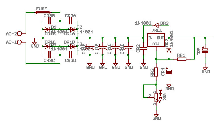
The power supply schematic for the MAX is based on the LM317, TO-220 voltage regulator. The film box cap - CR2, the tantalum caps - CR4, CR5, and the protection diodes DR2 and DR3 are right out of the data sheet recommendations. When combined with the 4x100uF power filtering caps - CR3A,B,C,& D, the Schottky rectifiers - DR1A, B,C,& D, and the ceramic snubber caps - CR3A,B,C,& D, the Millett Max power supply comes close to an equivalent of the familiar, high-quality Tangent STEPS DIY power supply. The only portion lacking is the STEPS transformer and its associated line voltage components. In the case of the MAX, the power may be supplied with a simple 24AC walwart. |
|
Referring to the LM317 diagram above, "Figure 1," the governing equation solves for the output voltage
capability for the voltage regulating circuit. The LM317 operates by maintaining 1.25V for
Vref. In the MAX, "R2" in the diagram is actually the 1K trimmer - RR3, plus the
2K ohm resistor - RR2. The MAX uses 120 ohms for the "R1" resistor (RR1 on the MAX BOM).
Assuming the highest and lower adjustment for the 1K trimmer and solving the equation for both
cases, the MAX power supply gives a voltage adjustment range of 22.1VDC to 32.5VDC.
Of course, this requires that the 24VAC walwart delivers sufficient voltage to allow this adjustment.
Experience with the proto builds has shown that 29V is just about the limit that can be supplied
with the recommended walwarts.
-- The recommended MAX power supply voltage is 27VDC. --
| |
|
|
|
|
