www.beezar.com

The following represents a method for MAX casework, but not the method. Some of you may have a drill press or some of you may use Front Panel Express. Still others may have access to a complete machine shop or wood shop. However, the following casework is based on the Hammond case in the MAX BOM and was accomplished with only a few inexpensive tools, along with simple items that can be found in most homes:
| |||
Drilling More Holes |
|||
Continuing with the same method (the backplate work was essentially identical to the frontplate), the top plate is next. The top plate is notable thicker in this size Hammond case than some of you previous Millett builders have experienced. However, except for the tube holes, the needed holes are small so drilling energy is not great. At a minimum, vent holes above each of the sinks are advised. The best scenario is to provide both an inlet and an outlet, but the vent holes in the top plate are best in lieu of both. You may or may not need them, depending on your bias setting. However, I can confirm that with BJTs biased at ~110mV (50ma) and a voltage supply set at 27VDC, the holes shown below work well. While the top plate may get fairly warm, there is no tendency for the bias or currents to increase.So, t he 3/16" diameter holes shown here and on the drilling template drawings are sufficient, as proven and tested with all those tip jacks in the back. Some builders have already built MOSFET versions of the MAX with no vent holes. Because of the negative temperature coefficient of the MOSFETs and the recommended 1-1/2" high sinks on the MOSFET version, this is possible. However, without ventilation, the BJTs and the regulator - with 1" high sinks - may continue to get hotter, requiring more current as they do so, until a thermal runaway condition may potentially exist. Vent holes in the top plate prevent that from happening. In addition, there are holes marked for each of the trimmer screws. They are offset as needed, depending on the orientation of the trimmer screws. These work reasonably well in conjunction with the tip jacks, but may be troublesome depending on available light. However, the alternative of completely disassembling the case makes this a reasonable compromise. A good trimmer tool, combined with small grommets can assist in making the alignment a bit easier. |
|||
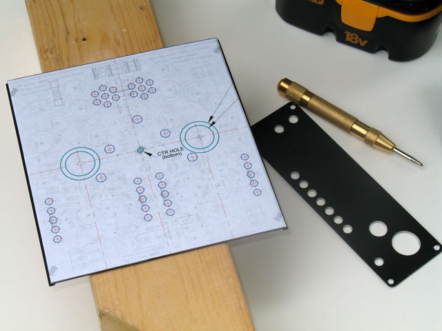 |
At left you see a MAX top plate ready for marking and drilling. The drilling template drawing has been applied as described in Part 1, using rubber cement on both paper and top plate. In the case of the endplates, you have a completely flate surface with radiused corners that provide a good guide for aligning the template when sticking it down. However, the top plate slot runners make alignment impossible with that method. Instead, mark the centerline on both the front and back edge of the top plate, and use the center lines of the drilling template for alignment. |
||
Also shown is the completed, drilled backplate and a new tool introduced in this part - an automatic center punch. |
|||
| I changed to the automatic center punch for two reasons - it was very cheap ($2.50 at Harbor Freight) and the point had worn into a small circle on my old manual punch, allowing the drill bit to still move around when starting holes. This one worked well: the center punches are sharp and easy to align. One caution: wear some hearing protection! The snap of the punch against the top plate might as well be a gun going off next to your ears! | 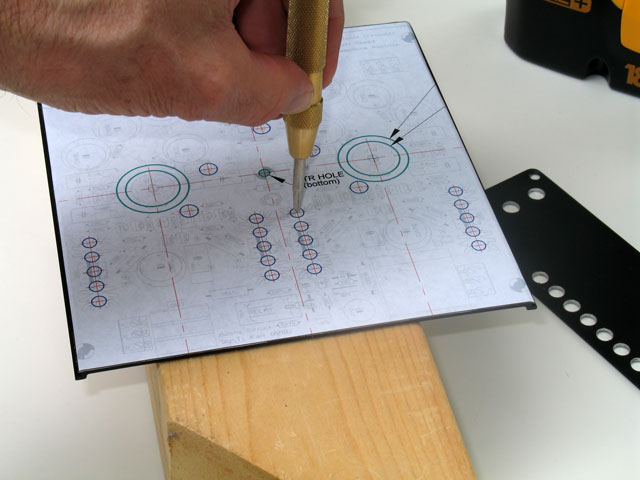 |
||
 |
Here we see the drilling template with center punching for all the holes completed. There is a center hole on the template for the PCB center hole, but that is for the bottom of the case and not used in this instance (more on that later). Also shown is the step drill bit I used. This particular bit has 3/16" diameter at the 3rd step. A drill press allows one to adjust the total vertical travel of the bit. However, we are doing this with a minimum of tools and a hand power drill. So, a piece of electrical tape just above the 3/16" step will help to keep us from pushing too far and making bigger holes than needed. |
||
Not counting the tube holes, this template has 39 holes to drill! This can get very tedious. Nevertheless, patience and tenacity will get you through it. We still aren't using a drill press, but there are a couple of things you can do to help keep the holes aligned: You will most likely find that the bit, even with its tip perfectly centered on the center punch, may drill slightly off-center. Consistency is the thing, though, and as long as you place the drill bit in the same relative position each time, and drill from the same direction each time, the holes will be consistent. In other words, start from the bottom and move vertically up with each line of holes. That way, any deviation is the same among all the holes. |
 |
||
Be careful to keep the bit clean, and remove it if too many chips start accumulating. Sometimes a quick blow will work to scatter the chips away from the hole being drilled. If you aren't careful to do this, enough waste metal may get wrapped up in the bit so that the paper is all torn, or worse - the top plate gets scarred up. |
|||
 |
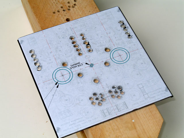
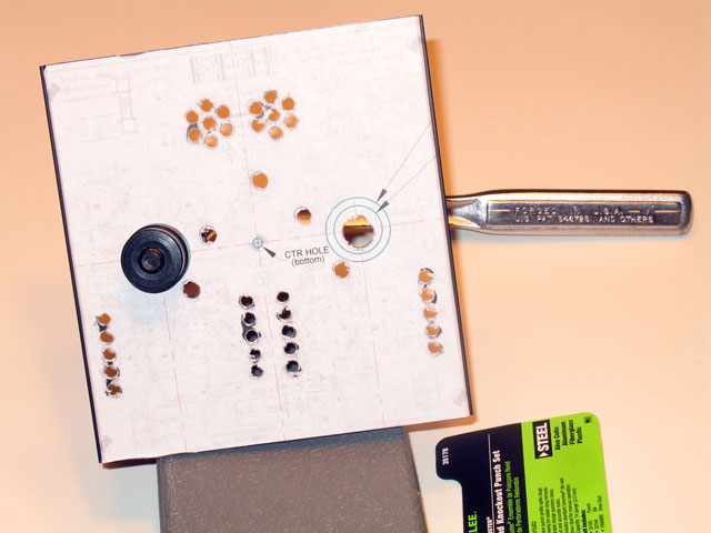
We can see the finished, drilled top plate from the bottom in this view. It looks pretty ugly - lots of metal chips, burrs, and uneven edges. That's OK - it's all on the side that doesn't show, and you will clean it up anyway. As long as the paper is in relatively good shape (refer to the pic above again), the top surface will be fine. About the misalignment when hand drilling - I can never keep the bit centered well enough on the tube holes. The holes are just too large, and there's just too much opportunity for the bit to "walk." |
||
| So, I auger out the holes about 10-20% larger than needed for the chassis punch (see below). This gives enough play in the draw-through bolt to let you align the punch die perfectly with the circle on the template.
|
|||
Punch the Tube Holes |
|||
What's known as a conduit/chasis punch is absolutely the best thing made for making the tube holes. The method I use, and the one also indicated on the drilling template, is to punch a 1" diameter hole, then snap in a plastic bushing. The plastic bushing is 3/4" O.D., and gives about 1/16" clearance around the tube, allowing for some tube misalignment and slightly bent pins. The bushings may be ordered from the usual electronic parts sources, or may also be purchased from your local hardware store in those ubiquitous small parts aisles. Needless to say, the tube locations must be tightly coordinated from the very beginning of your build. The drilling template on the MAX website assumes the front of the MAX PCB is flush with the front edge of the case slots. However, this assumes 1) an RK27 pot, 2) two spacer washers on the board-mtd Neutrik jack, and 3) you much make every effort to line up the tube sockets when you solder them to the board. This is done through trial and error by slightly bending the pins until they are completely symmetrical around the socket center, prior to soldering them to the board. If you have taken these items into account, then there's no reason you can't get the tube holes lined up in their exact spot. Colin's design also makes this easier, but lining up the sockets along the same centerlines as the pot and the jack, and symmetrical with the centerline of the entire amp. |
|||
Shown here are a couple of choices for the chassis/conduit punches - one not so good, the other one fantastic. Guess which one costs the most? The one on the right - the Greenlee 1" punch - is simply wonderful to use. The set on the left cost me one-fourth as much as the single Greenlee punch. It's a set from Harbor Freight and has four punches in various diameters. You can make these work, and I have used them on a few revMH Milletts. However, the problem is that the threads are not precise enough to track the punch straight through the hole. |
 |
||
| The force is great enough that the punch will get twisted a bit sideways, while you wrestle with a 1/2" breaking bar (larger than the one shown below) and attempt to somehow support the plate while keeping it from getting bent. There were times when I thought I'd have a Hammond top plate with the punch part-way through as a permanent sculpture to add to my desk. Note also that the 2nd punch - the 1" - is actually 1.112" something in diamter. You will need some sort of snap ring on the other side of the plastic bushing to keep it in place if this punch is used. |
|||
 |
The Greenlee punch may be ordered from Mouser and other sources. I got mine from Grainger. Be careful to measure the O.D. when you purchase these punches. many of them are made for conduit, and the O.D. is a nominal value that may be quite a bit larger than the published size. Here you see the draw-through bolt with its large hex head, the ball-bearing thrust washer, the die, and the threaded punch on the other side. This one (Slug Buster) has a punch with two points, and a knife edge in the middle tapering from both edge points. |
||
| In this pic I have my handy Craftsman 1/2" ratchet wrench with appropriate sized socket for the punch bolt. The really nice thing about the Greenlee punch is that you can literally hold the top plate with your hands while you turn the wrench or vise-versa. | 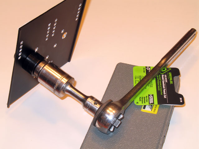 |
||
 |
Here is another view of the back side of the punch. This is the part that you want to try to line up exactly with the circle on the template - both punch points should be touching the circle and the center of the punch at the center of the circle. Eyeballing it is adequate if you get those punch points on the circle. Be very careful moving the punch around when aligning! The punch points are sharp enough to scratch right through the paper and onto the top plate surface |
||
| Here is the completed, punched and drilled top plate. You can see the punch at the bottom with the top plate slugs from the tube holes. | 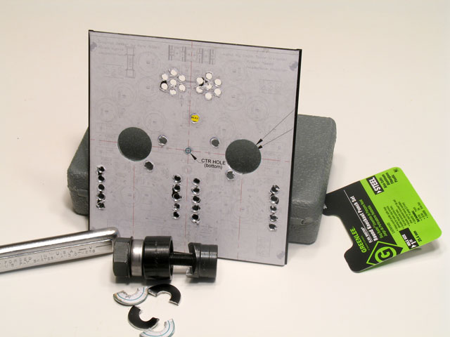 |
||
 |
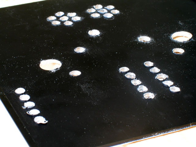
And voila! Pull off the paper template to reveal the cleanly drilled and punched top plate surface below. Again, if you've taken care of the paper and not let that tear up too badly, there's no reason to expect that any damage has been done to the top plate finish. | ||
The top plate with the template completely removed. In most cases, you will find that the rubber cement pulls off almost completely with the paper. There is very little left on the work surface. Any remaining is easily rubbed off with a finger. Look closely and you will see a very minimum clearance between the right tube hole and the right DB trimmer. 3/16" holes may be better for the trimmers in this case, but it's an either-or prospect: the 3/16" trimmer holes make it easier to align the trimmer tool, but if the holes themselves are not perfectly positioned, then it makes it harder. The holes shown here are 1/4". |
 |
||
