www.beezar.com

The following represents a method for MAX casework, but not the method. Some of you may have a drill press or some of you may use Front Panel Express. Still others may have access to a complete machine shop or wood shop. However, the following casework is based on the Hammond case in the MAX BOM and was accomplished with only a few inexpensive tools, along with simple items that can be found in most homes:
| |||
Mockup First |
|||
| There are a couple of methods for marking and sizing holes. Some mark directly on the endplates, others cover the endplates with masking tape and mark on the tape. Either method works well. I like to use paper templates, instead. CAD files make this really convenient. However, even if you do not have access to CAD, you can manually draw up a template. The advantage to this is the ability to do a mockup. | |||
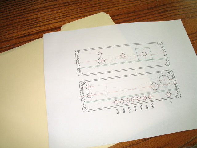 |
At left you see a printout of the CAD templates provided here on the MAX website. Except for the front plate pot shaft and the board-mtd headphone jack, these templates already have a suggested layout for typical components. However, there's no reason you can't print these out and then mark up your own on the same printout. The important point here is to make the mockup so to confirm your own choice of connectors, jacks and switches and their locations. | ||
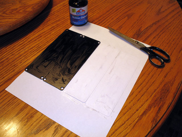
| Once you have your endplates drawn to satisfaction, you need to glue them to some sort of backing. The purpose of the backing is to provide enough substance to hang all the connectors and mount the mockup to the case. Pictured here and above is a simple file folder. I coat both the paper drawing and the manilla folder with rubber cement and let them dry completely. | 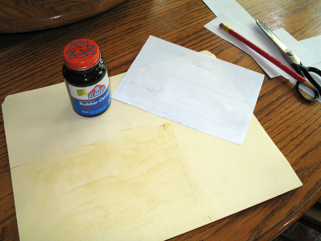 |
||
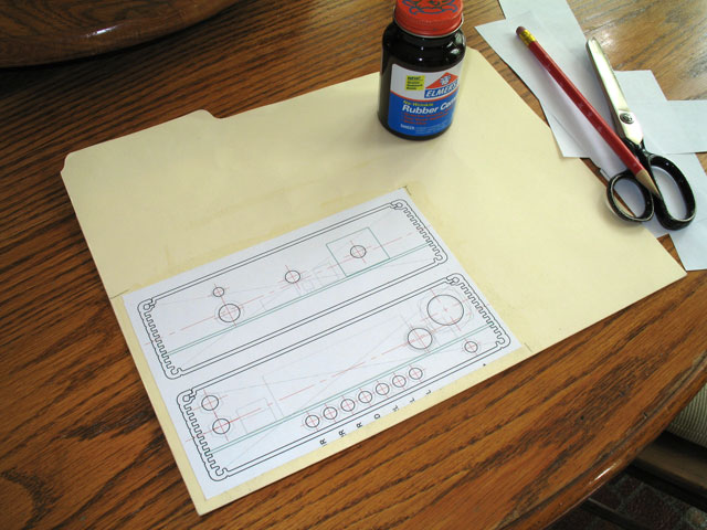 |
The templates are glued down to the file folder. Afterwards, they are carefully cut out and trimmed along the border lines. | ||
| An ice pick works for the endplate mounting holes, while a paper hole punch makes a good round nibbler. Quarter-inch holes are one punch, others can be nibbled out to the edges. Eventually you can make a complete "cardstock" endplate. Screw your connectors onto the cardstock endplate and you're ready to see how it fits up with the rest of the case and the circuit board. | 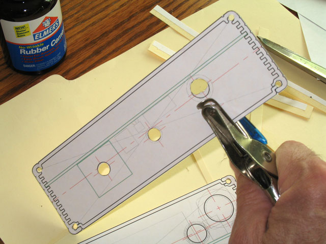 |
||
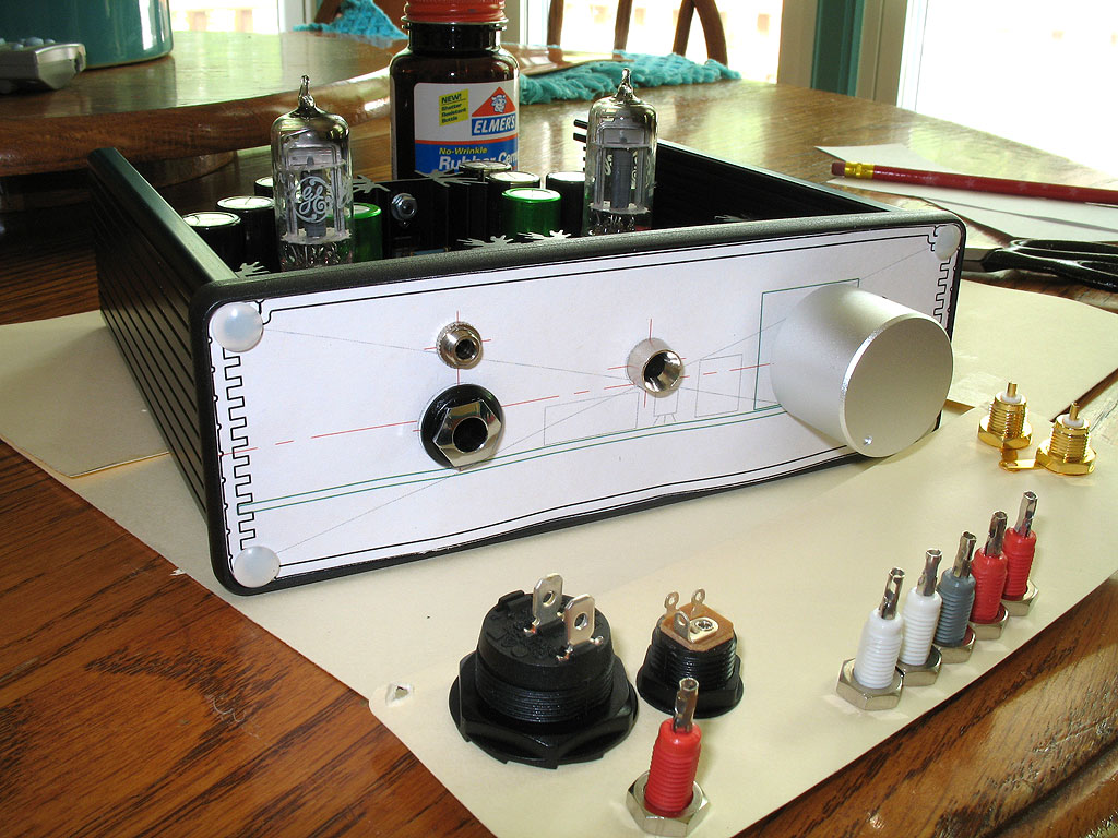 |
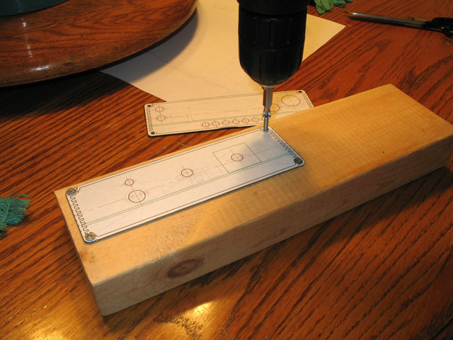
Here's the front "plate" fitted up to the case with the headphone jack and volume pot shaft locations confirmed. The MAX is the same as the revMH Millet in that both the volume pot and headphone jack are soldered to the board and their location is fixed. The mockup is critical in proving the correct dimensions prior to actually drilling the endplate. The template drawings included here on the MAX website have been confirmed and tested for correct locations of these two critical components relative to the recommended Hammond case. To the side you can see the cardstock backplate, with the connectors attached. | ||
| Here's another view of the backplate with connectors: power switch, power socket, RCA jacks, and tipjacks for all the bias points. The power supply voltage adjust tip jack is off to the side to differentiate itself from the gray ground and the left and right channel tube and DB bias points. | 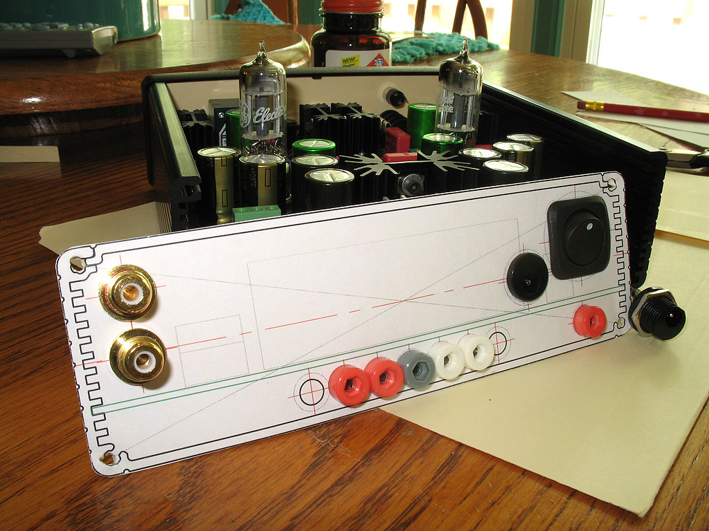 |
||
Drill for Real |
|||
 |
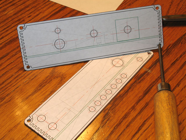
Repeating the process with the "real thing," here you see the two endplates after painting with rubber cement. The paper template will painted after cutting out, so the rubber cement doesn't foul the scissors. | ||
Cutting the templates out to the exact shape helps to allign them almost exactly before pressing down on the plates. Careful attention is required here - you can do some very limited lifting and removal, but once pressed down, that's it - you'll have to start over and make another template if you get it wrong. That just means a little more paper and some rubber cement, though, so much better still than a mis-placed hole drilled in the endplate (been there/done that, too). An ice pick works well to poke out the mounting holes. This is useful, because there's no reason we can't use the mounting holes as clamps for drilling as shown below - |
 |
||
 |
The standard Hammond case uses #6 screws for fastening the endplates to the case. That means we can use #6 wood screws to secure the endplate to a scrap 2x4. This does many things all at once - clamps the endplate, provides a means of rigidly clamping the whole assembly with no marks to the endplate, and it provides a great backing for drilling holes without bending. I used #6 x 1/2 screws - pennies for 4-8 of them. If your 2x4 is big enough, go ahead and mount both endplates. Mine wasn't so I did them one at a time. |
||
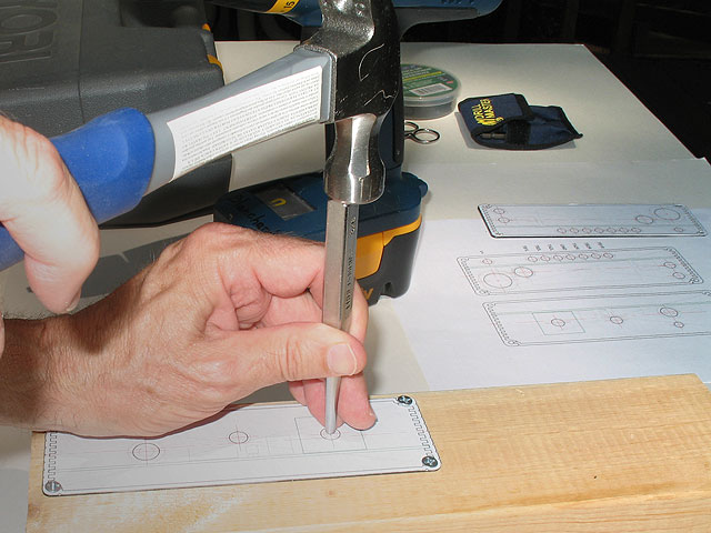
After screwing the endplate down to the 2x4, the next step is center punching starting marks for the drill. Any drill bit will "walk" slightly unless you provide an indentation for the tip of the drill bit. This allows the bit to grip the metal and start cutting before it has a chance to move. If we were using a drill press, you don't have to do this (depending on the quality of the press). However, in the interests of all the MAX builders out there, we're trying to do this with only a hand cordless drill, so the center punching is needed. This one is a typical Craftsman center punch that came in car tool set I purchased many years ago. Place it on the intersection of the centerlines for a hole, and give it a whack with the hammer. |
 |
||
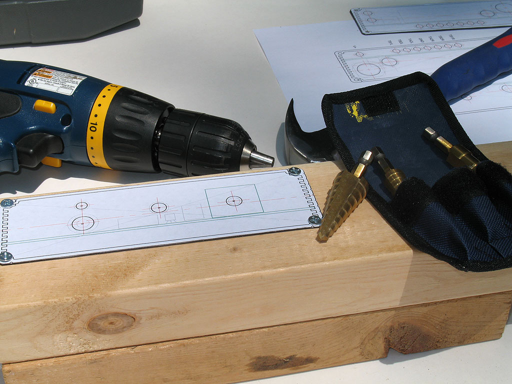 |
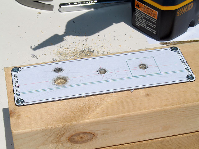
Here we see the holes center punched. The next step is to select the proper drill bit - a step drill bit, for sure. These are three that come in a pouch for $9.99 at Harbor Freight. Not the best quality and they have their own centering errors, but more than adequate for the MAX case is proper care is taken. |
||
| Drilling the holes in earnest. That's a piece of black electrical tape on the bit. It's a good idea to determine the size step on the bit for the diameter hole you need to drill, then apply the tape to the next step up. This helps prevent you from drilling too deep, which in the case of a step drill, would mean a hole too big. | 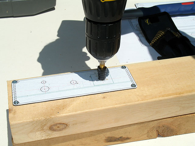 |
||
 |
All of the holes for the front end plate are drilled here: RK27 pot shaft, T-1-3/4 LED panel bezel, Neutrik board-mounted jack, and 3.5mm barrel type jack at the top. | ||
| ... and we remove the paper template from the surface of the endplate. | 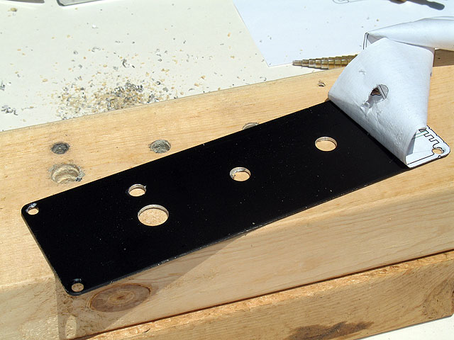 |
||
 |
This image illustrates typical results - a very nicely preserved surface finish - protected during work by the paper template. Also shown are the burrs that may develop on the back side and in the hole. | ||
| I use a Leatherman to clean up the holes. The knife portion is more than enough to cut off the edge trim on the edge of a hole, and the awl makes an excellent little planer on the inside circumference of the holes. Both work together to give smooth, burr-free holes. | 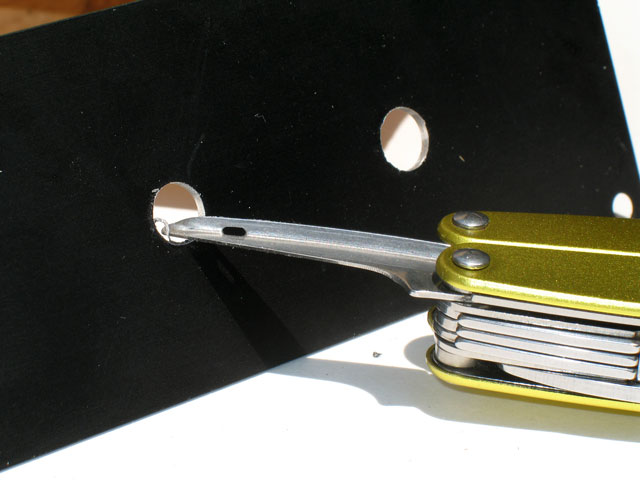 |
||
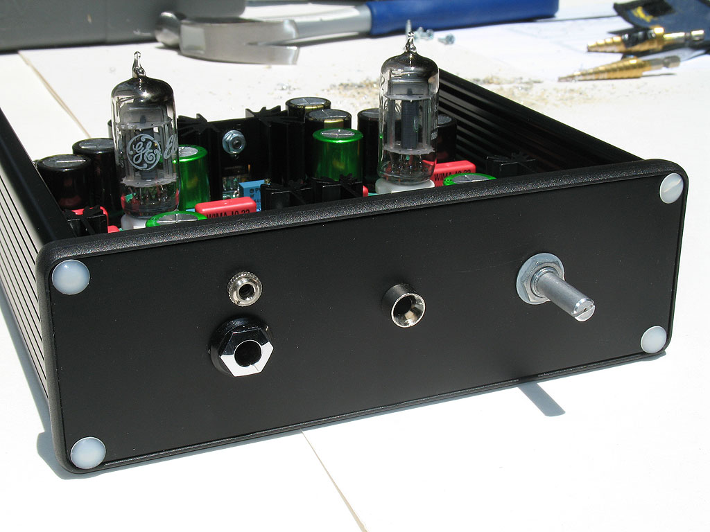 |
Here's the completely front plate temporarily attached to the front of the case. Yay, MAX! | ||
