| As stated previously, the DoodleBug USB Isolator is not very complicated as some designs go. There is only a power input, a USB input, and a USB output to consider. One thing to do prior to applying power, however, is to make a final check of the PCB and your solder connections:
- Check that the pins are all soldered on the IC1, IC2, and the two USB jacks.
- Check that all SMD passive parts are solderd on both ends.
- Check that all through-hole parts have both leads soldered.
If all that checks out, then apply power - do the LEDs light? If so, you're ready to set the voltage.
Output voltage is set on the DoodleBug by using your meter to measure the voltage at the test points labeled, "+5 Volts" and "Ground."

A word about the output voltage -
The USB 2.0 standard requires voltages from hubs that can vary as low as 4.4VDC to as high as 5.25VDC. The low voltage specification is unfortunate for audiophiles, because voltages as low as 4.4VDC can be extremely detrimental to DAC operation. The PupDAC for instance, uses a 4.75VDC regulator to provide the analog output for the PCM1794 DAC chip. Even an LDO (Low DropOut) regulator needs more than the 4.75VDC to provide a regulated 4.75VDC (it needs some headroom, in other words). If the USB 2.0 standard allows for voltages as low as 4.4VDC, then there's no chance that some designs such as the PupDAC will see regulated voltage above that mark - if the USB source is allowed to go to voltages that small (but still be OK by the standard!). Note that we want regulation, because that's what produces the lowest noise.
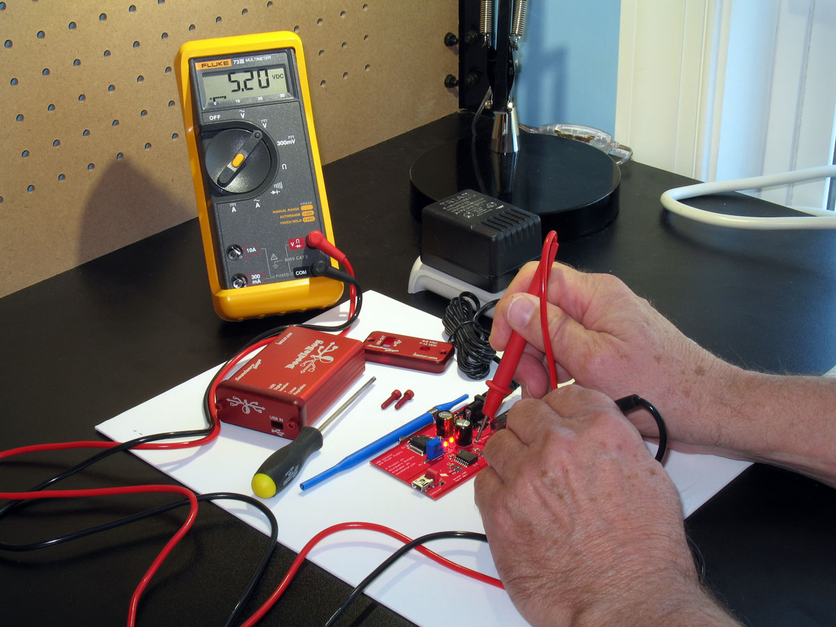
In order to ensure the highest-possible headroom available for any USB device's regulation, the DoodleBug should be set to the highest voltage allowed by the USB 2.0 standard. The voltage output is adjustable on the DoodleBug, because walwarts may vary widely and so does line voltage, although to a lesser extent. In fact, the diodes, resistors, and LEDs on the DoodleBug PCB may vary, too. So the output is adjustable for this reason.Here we see the DoodleBug all setup for voltage adjustment. The meter is currently not connected to the test points, so it registers .000 VDC.
 |
Place your probes in the test points and check for the voltage. If it's below 5.25 VDC, then adjust the trimmer screw of VR1 a few turns. Check the voltage. If it dropped, then turn the trimmer screwe of VR1 twice as many turns the other way. Check the voltage again. It should be going up. Adjust for the highest voltage you can attain that's closest to 5.25 VDC - without going over that voltage if you want to adhere to the USB standard..
NOTE: If you cannot reach 5.25VDC, then stop at the highest voltage you obtained. Refer to the Tweaks page if you need to get more voltage. My DoodleBug (TomB) was able to adjust to 5.20 VDC using the Beezar kit-production parts, . That's not all the way to 5.25VDC, but close enough, considering the variances in meters and line voltage. Note that voltage is achieved even though the Beezar kit-produced parts selection uses a 9VDC walwart and I populated all of the rectifiers. If you truly want higher voltage and you are using the kit parts, then you may want to jumper some of the rectifiers. Refer to the Tweaks page for details.

|