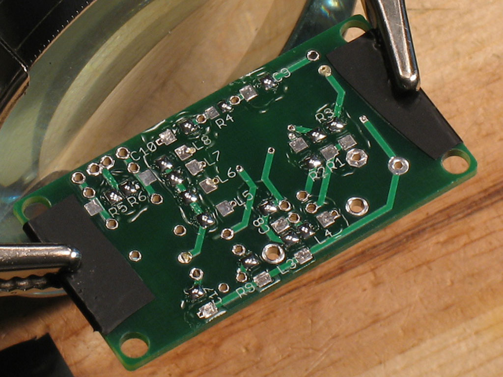
STEP 11 - Apply Flux Pen and Solder to SMD Anchor Pads
Similar to the top side, apply flux using the flux pen to the part pads. After the flux is applied, apply a bit of solder to the pads you want to be anchors for the parts. Your choice - there's no ground plane on the bottom.
Here's what your board should look like, after applying the flux and solder to some anchor pads.
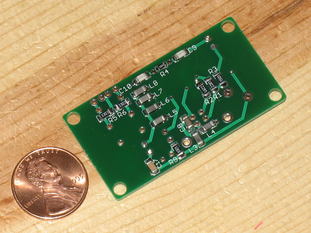
STEP 12 - Solder the SMD Parts to the Bottom of the Board
Similar to the top side of the board, heat an anchor point where you've applied some solder. Using tweezers, move the end of the part into the melted solder. Let cool, release the tweezers. Go back and apply solder/heat in a normal manner to solder the other ends of the parts.
NOTE: Be careful of C8. That's the largest part on the bottom of the board. It more or less forms a square cylinder, so not only is it a bit difficult to tell side from top or bottom, but it's also a bit difficult to get flat when soldering. You should probably do this part first.
The photo above shows the finished board - at least finished except for the through-hole parts. Why leave it in this state and not finish yet with the through hole parts? Step 13 has the answer.
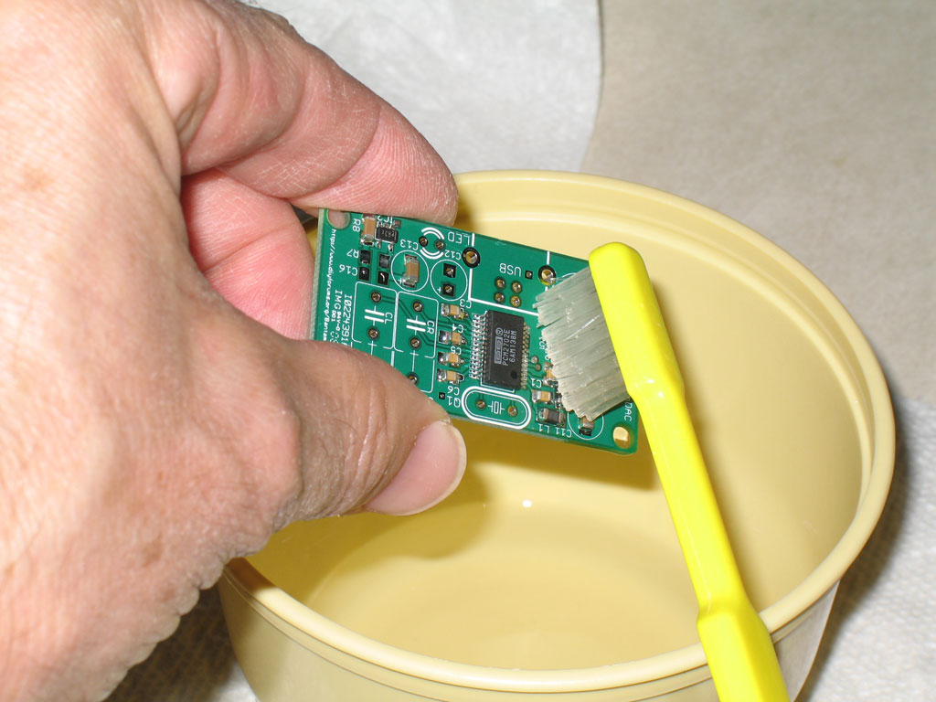
Step 13 - Immerse and Rinse the BantamDAC PCB
The reason we've waited before installing the through-hole parts is that at this point, we can simply drop the board into a cup/dish partially filled with the same 90% alcohol that we use for rinsing. Only enough alcohol is needed to immerse the board. This makes cleaning a snap and gets out flux that may even be trapped beneath the PCM and TPS chips. Still, a little bit of brushing will help to remove the worst of the cooked-on flux.
Dry thoroughly in preparation for the next step.
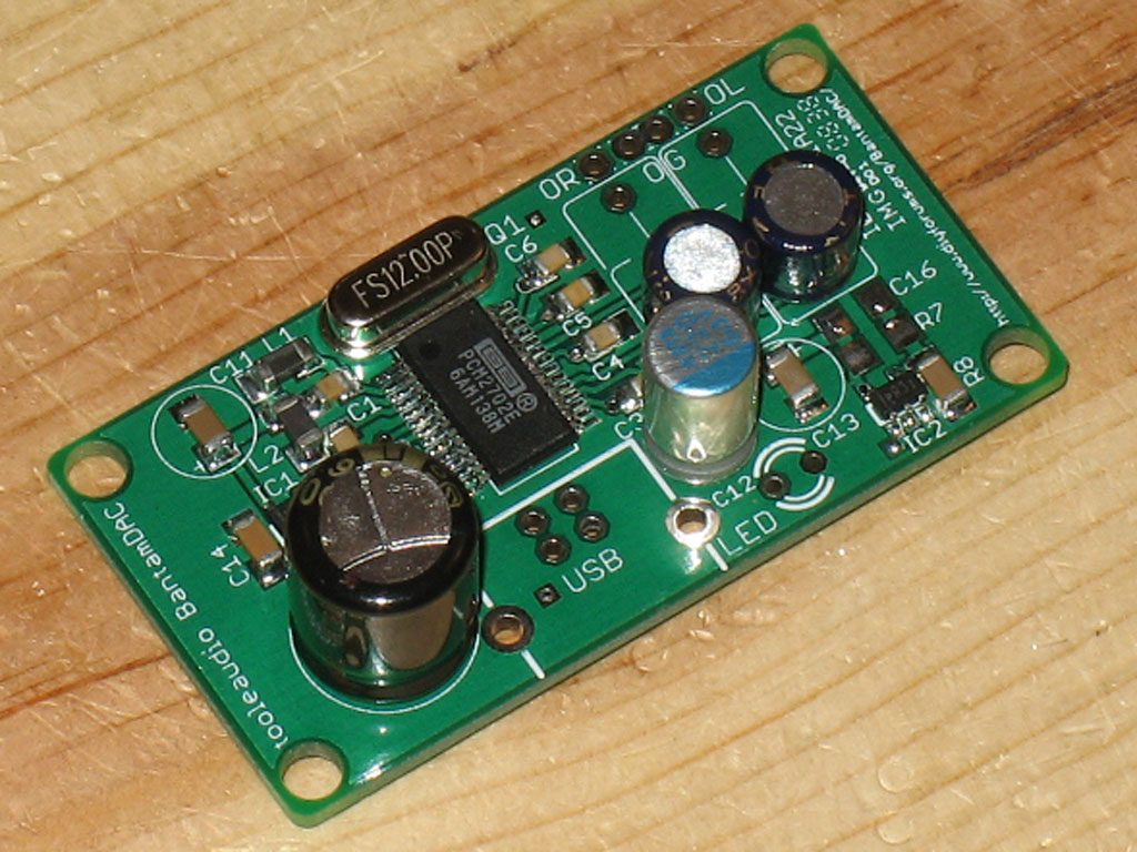
Step 14 - Install the Through-Hole Parts
Finally, you get to install the through-hole parts. As with any through-hole PCB, install the shortest parts first, then end with the tallest:
The 12MHz crystal (the BantamDAC uses a low-profile crystal)
Black Gate or other film/electrolytic coupling caps, if used (CL and CR).
The ultra-low ESR cap, C12.
The USB connector, if used.
The power cap, C7.
Note that if using the USB Type "B" jack, the snap pins are a tight fit on the BantamDAC PCB. It will help if you bend the tabs slightly straight before attempting to snap into the board.
This board was used for the BantamCableDAC, so the USB jack is left unpopulated. Also, the height of the LED was adjusted once the board was fitted to the case, so it was added later.
You're finished populating the BantamDAC PCB!!
file last changed:Monday, October 13, 2008 7:00:00 AM
Please contact the BantamDAC webmaster for questions about these web pages.